Download

1 / 30
300 likes | 530 Views
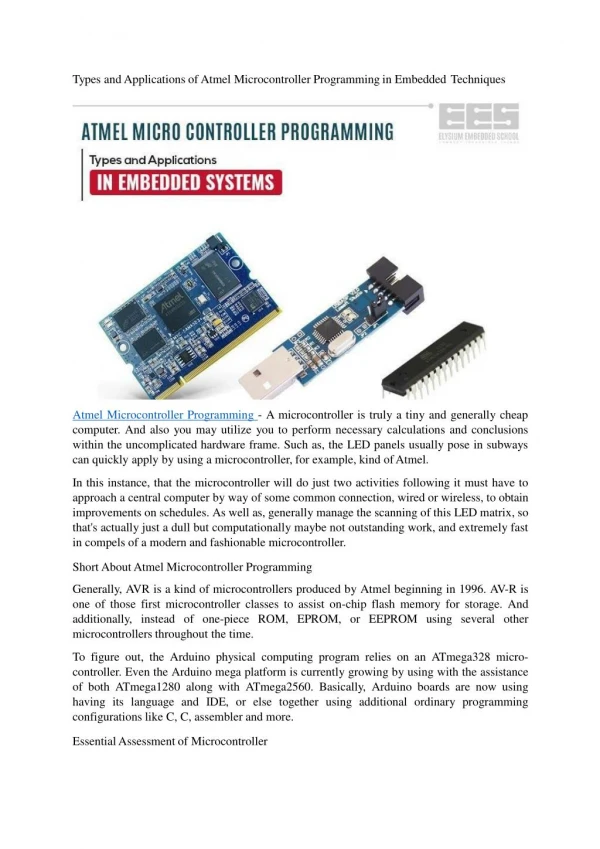
Embedded Systems Programming Custom sensors for the use with Atmel ATmega8535 microcontrollers and the Kanda STK200 board Designed by Richard Anthony University of Greenwich. 1. New sensors for the ATmega8535. Light Sensor Connects to Analogue input ADC7 (pin 7 of Port A)

E N D
Embedded Systems Programming Custom sensors for the use with Atmel ATmega8535 microcontrollers and the Kanda STK200 board Designed by Richard Anthony University of Greenwich 1
New sensors for the ATmega8535 Light Sensor Connects to Analogue input ADC7 (pin 7 of Port A) Reading increases as light intensity increases Embedded Systems Programming II Richard Anthony, Computer Science, The University of Greenwich
New sensors for the ATmega8535 Floor-Switch Sensor Connects to Digital input (bit 0 of any port) When the mat is stepped on, the switch operates Embedded Systems Programming II Richard Anthony, Computer Science, The University of Greenwich
New sensors for the ATmega8535 Passive Infra-Red (PIR) Sensor Connects to Digital input (bit 2 of any port) When a person moves, in detector range, the internal switch operates Embedded Systems Programming II Richard Anthony, Computer Science, The University of Greenwich
New sensors for the ATmega8535 Magnetic-Switch Sensor Connects to Digital input (bit 1 of any port) When the magnet is moved in / out of range, the switch operates Embedded Systems Programming II Richard Anthony, Computer Science, The University of Greenwich
New sensors for the ATmega8535 Twin Variable Resistor Sensor Connects to Analogue inputs ADC2 and ADC3 (bits 2 and 3 of port A) Rotating the dials changes the analogue resistance values 6 Embedded Systems Programming II Richard Anthony, Computer Science, The University of Greenwich
Peripherals – Thermistor (2) Our custom temperature sensor can be connected to bit 6 of port A. (Must be used on port A because it is an analogue device and needs to be sampled using the ADC). 7 7 Embedded Systems Programming II Richard Anthony, Computer Science, The University of Greenwich
Peripherals – Thermistor (2) Thermistor temperature sensor probe calibration (8-bit values read as ADCH, i.e. most significant 8 bits) 8 8 Embedded Systems Programming II Richard Anthony, Computer Science, The University of Greenwich
Peripherals – Humidity Sensor Our custom Humidity sensor can be connected to bits 3, 4, 5 of port A (uses all three bits). (Must be used on port A because it is an analogue device and needs to be sampled using the ADC).
Peripherals – Sounder Used in PCs, Christmas cards, alarm clocks …. Low output current needed - can be driven directly from a parallel port pin. Our custom sounder device is connected to bit 3 of the port. You need to configure the pin for output and provide a pulse on the port bit 3. See the Loudspeaker demonstration project provided. 10 Embedded Systems Programming II Richard Anthony, Computer Science, The University of Greenwich
Peripherals – Motor with shaft encoder and H/W Interrupt generation Motor Can be driven via bit 3 of any port (‘1’ provides power to the motor). Primarily designed for PWM using Timer/Counter0. Timer 0 Output Compare Match Output OC0 is the alternate function of Port B bit 3. Motor can reach speeds exceeding 100 Revolutions per Second (6,000 RPM). Motor stalls if driven with a duty cycle less than 29% (approximately 8 RPS). Shaft Encoder Comprises a ‘Slotted-Opto Switch’ (which detects when its light beam is broken) and a rotor with four cut-outs, enabling detection accuracy of ¼ rotation (i.e. 90 degrees). If measuring rotational speed, four pulses represent 1 revolution. The output of the Slotted-Opto Switch is connected to bit 2 of any port. Primarily designed to generate a Hardware Interrupt INT0, which is the alternate function of Port D bit 2. 11 11 Embedded Systems Programming II Richard Anthony, Computer Science, The University of Greenwich
Slotted Opto Switch Rotor Motor Peripherals – Motor with shaft encoder and H/W Interrupt generation Connections to Port B and Port D 12 12 Embedded Systems Programming II Richard Anthony, Computer Science, The University of Greenwich
Slotted Opto Switch Transistor driver circuit for motor Rotor Motor Peripherals – Motor with shaft encoder and H/W Interrupt generation 13 13 Embedded Systems Programming II Richard Anthony, Computer Science, The University of Greenwich
Peripherals – Shaft encoder IR LED Infrared light beam IR sensitive transistor (under rotor) Embedded Systems Programming II Richard Anthony, Computer Science, The University of Greenwich
There is also a simpler motor rig that does not have the optical feedback system Details will be added soon
8 Analogue outputs, one per stage to allow experiments Bit 0 8 bit Digital data input Bit 7 Resistors Digital Signal Processing – D-to-A conversion with a resistor ladder A simple 8-bit R-2R resistor ladder (connects to any port, uses all 8-bits configured as outputs) Converts a Digital value in the numerical range 0 – 255 into an Analogue value in the range 0 Volts to 5 Volts 16 16 Embedded Systems Programming II Richard Anthony, Computer Science, The University of Greenwich
Digital Signal Processing – D-to-A conversion with a resistor ladder Oscilloscope Earth connection 17 17 Embedded Systems Programming II Richard Anthony, Computer Science, The University of Greenwich
Digital Signal Processing – D-to-A conversion with a resistor ladder Oscilloscope Earth connection 18 18 Embedded Systems Programming II Richard Anthony, Computer Science, The University of Greenwich
Peripherals – Accelerometer and X-Y axis Bar LEDs Embedded Systems Programming II Richard Anthony, Computer Science, The University of Greenwich
Peripherals – Accelerometer and X-Y axis Bar LEDs Embedded Systems Programming II Richard Anthony, Computer Science, The University of Greenwich
Output device - SERVO Converts a control signal from a single digital output port pin into a precise rotational position (angle). PWM is used to generate the control pulse width in the range 0.5ms – 2.5ms (1.5ms pulse indicates the ”neutral“ / central position). Rotation: 180 degrees. 21 Embedded Systems Programming II Richard Anthony, Computer Science, The University of Greenwich
Peripherals – Servo adapter board Power (from supply) 5Volt to 6Volt To Microcontroller port To Servos Ground from supply (0Volt) Embedded Systems Programming II Richard Anthony, Computer Science, The University of Greenwich
Peripherals – Servo adapter board Signal (PWM pulse) Power 5Volt to 6Volt Ground (0Volt) To Servo Embedded Systems Programming II Richard Anthony, Computer Science, The University of Greenwich
Peripherals – Servo adapter board Two servos connected, using both Timer1 PWM channels Embedded Systems Programming II Richard Anthony, Computer Science, The University of Greenwich
Peripherals – InfraRed receiver (RC5 command receiver, as in TV remote controls) InfraRed receiver
Peripherals – Radio Frequency Identification (RFID) reader “Tag read” Indicator LED RFID reader RFID tag
Peripherals – Keypad Provides a simple means of numerical data or control input. The Keypad has 12 buttons arranged in a 4 Row * 3 Column Matrix: 28 Embedded Systems Programming II Richard Anthony, Computer Science, The University of Greenwich
LCD display panel Peripherals – Liquid Crystal Display (LCD) The LCD provides a versatile means of displaying alphanumeric data and messages (such as error codes, status messages, and user instructions). The LCD can display 2 rows of 16 characters. 29 Embedded Systems Programming II Richard Anthony, Computer Science, The University of Greenwich
Peripherals -Seven Segment display 30 Embedded Systems Programming II Richard Anthony, Computer Science, The University of Greenwich