Download

1 / 33
0 likes | 19 Views
The Moller Spectrometer project involves two coil designs - DS Hybrid Torus and DS Segmented Torus. By using the Pugh matrix, criteria such as design goals, fabrication complexity, assembly, and operation were evaluated. Both designs satisfy physics and engineering requirements, but the Segmented Torus is found to be less complex to fabricate and assemble. Although the segmented design may require more time for certain processes, the schedule impact is minimal. Opting for the Segmented Torus design may increase costs due to additional materials.

E N D
Moller Spectrometer Moller Spectrometer Down Stream Toroid Coil Design Down Select Decision J. Mammei / R. Fair v2.00 – 12.15.2020
Introduction to the two DS coil designs Coil engineering process How did we use the Pugh matrix Physics Criteria – refer to Juliette’s slides Engineering Criteria Design, Fabrication, Assembly, Operation Schedule Impact Cost Impact Summary and Conclusion
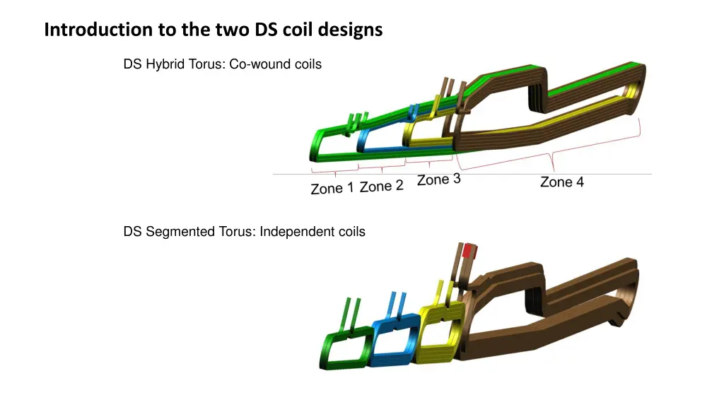
Introduction to the two DS coil designs DS Hybrid Torus: Co-wound coils DS Segmented Torus: Independent coils
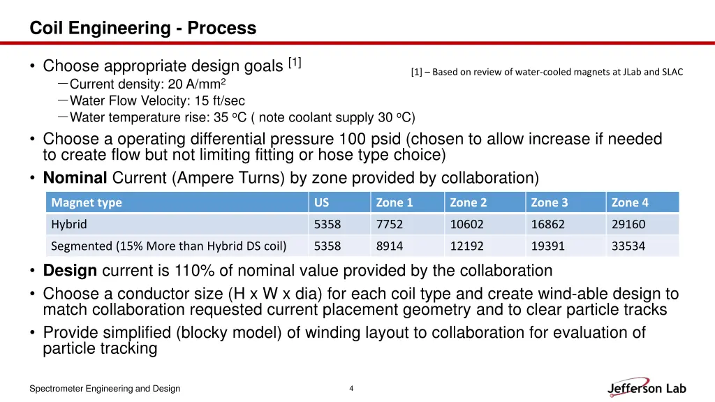
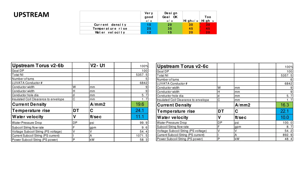
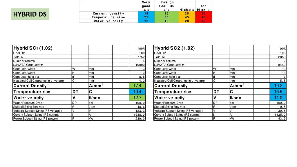
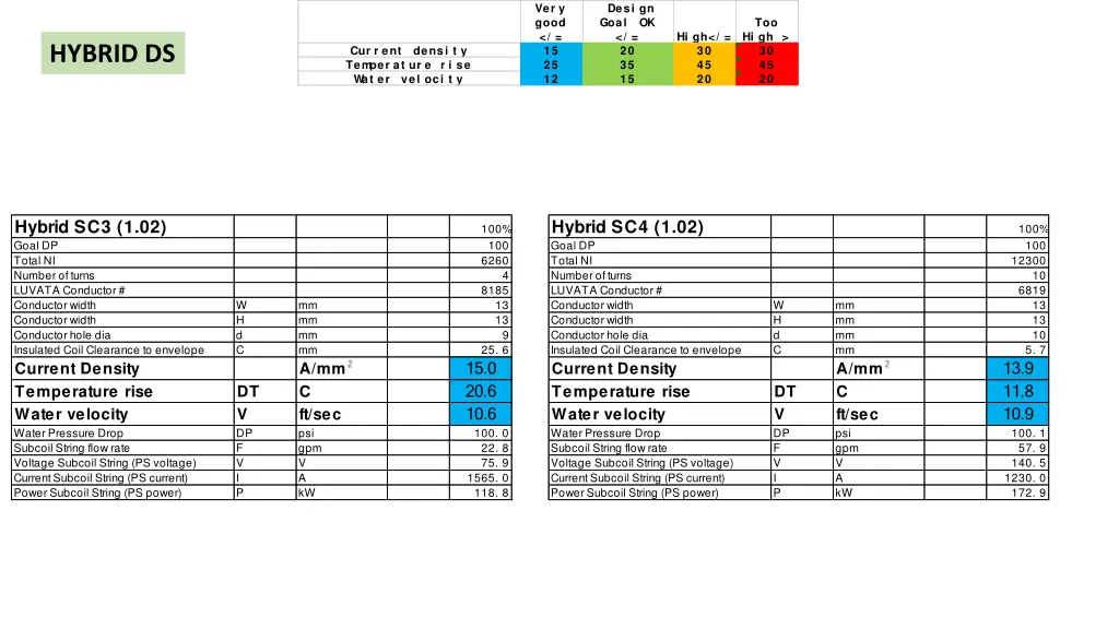
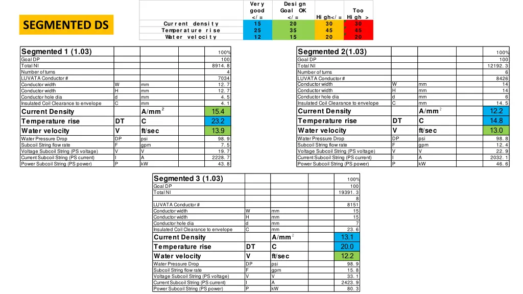
Coil Engineering - Process • Choose appropriate design goals [1] -Current density: 20 A/mm2 -Water Flow Velocity: 15 ft/sec -Water temperature rise: 35 oC ( note coolant supply 30 oC) • Choose a operating differential pressure 100 psid (chosen to allow increase if needed to create flow but not limiting fitting or hose type choice) • Nominal Current (Ampere Turns) by zone provided by collaboration) [1] – Based on review of water-cooled magnets at JLab and SLAC Magnet type US Zone 1 Zone 2 Zone 3 Zone 4 Hybrid 5358 7752 10602 16862 29160 Segmented (15% More than Hybrid DS coil) 5358 8914 12192 19391 33534 • Design current is 110% of nominal value provided by the collaboration • Choose a conductor size (H x W x dia) for each coil type and create wind-able design to match collaboration requested current placement geometry and to clear particle tracks • Provide simplified (blocky model) of winding layout to collaboration for evaluation of particle tracking Spectrometer Engineering and Design 4
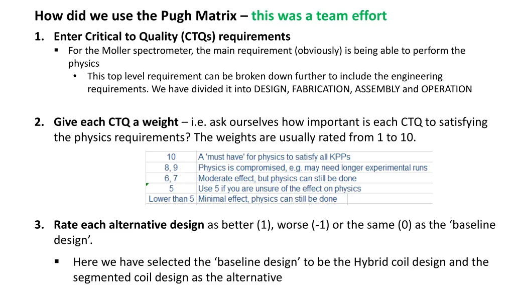
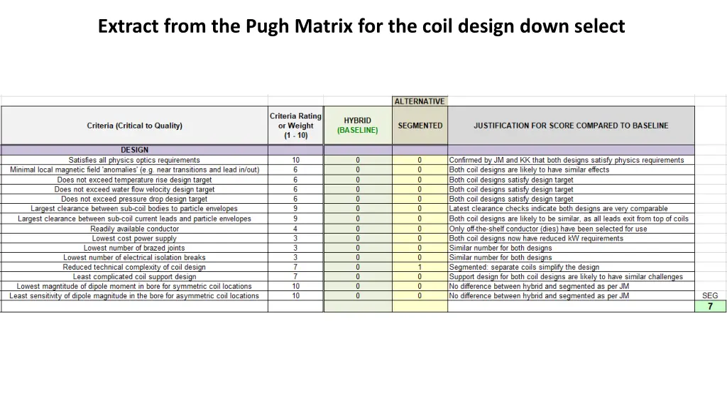
How did we use the Pugh Matrix – this was a team effort 1. Enter Critical to Quality (CTQs) requirements For the Moller spectrometer, the main requirement (obviously) is being able to perform the physics • This top level requirement can be broken down further to include the engineering requirements. We have divided it into DESIGN, FABRICATION, ASSEMBLY and OPERATION 2. Give each CTQ a weight – i.e. ask ourselves how important is each CTQ to satisfying the physics requirements? The weights are usually rated from 1 to 10. 3. Rate each alternative design as better (1), worse (-1) or the same (0) as the ‘baseline design’. Here we have selected the ‘baseline design’ to be the Hybrid coil design and the segmented coil design as the alternative
PHYSICS CRITERIA Juliette
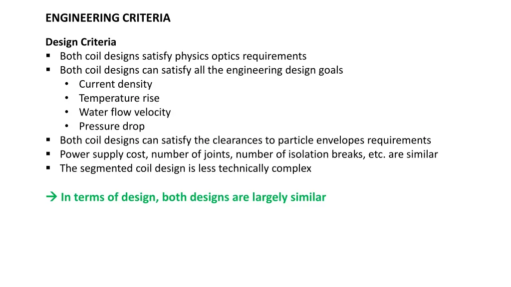
ENGINEERING CRITERIA Design Criteria Both coil designs satisfy physics optics requirements Both coil designs can satisfy all the engineering design goals • Current density • Temperature rise • Water flow velocity • Pressure drop Both coil designs can satisfy the clearances to particle envelopes requirements Power supply cost, number of joints, number of isolation breaks, etc. are similar The segmented coil design is less technically complex In terms of design, both designs are largely similar
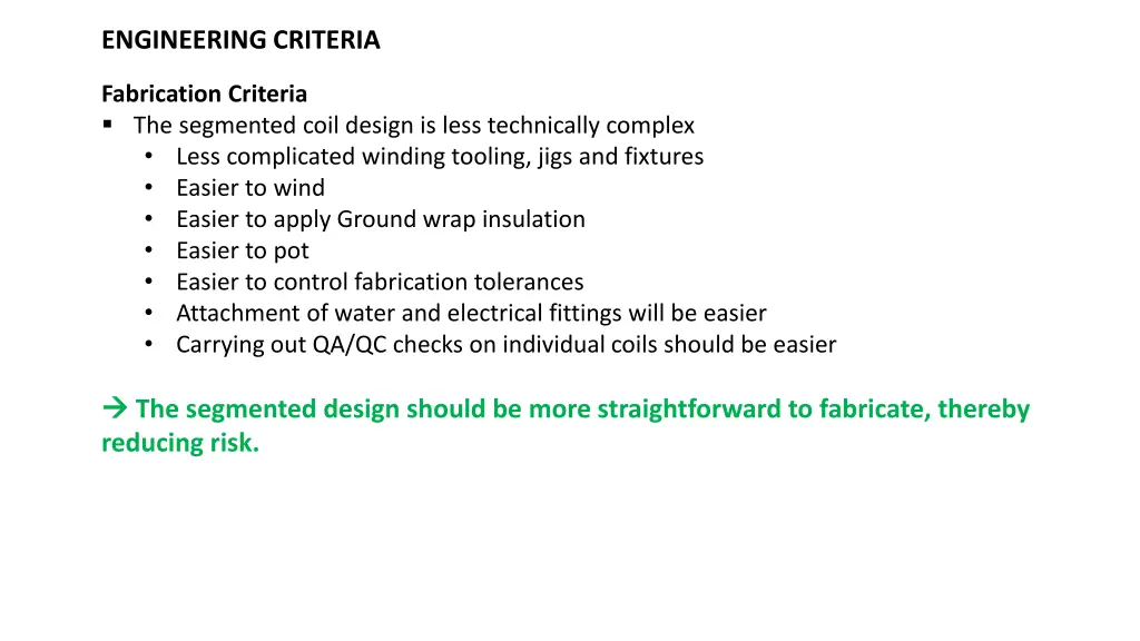
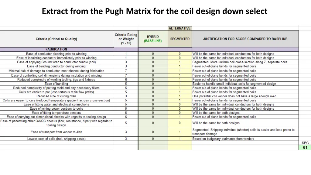
ENGINEERING CRITERIA Fabrication Criteria The segmented coil design is less technically complex • Less complicated winding tooling, jigs and fixtures • Easier to wind • Easier to apply Ground wrap insulation • Easier to pot • Easier to control fabrication tolerances • Attachment of water and electrical fittings will be easier • Carrying out QA/QC checks on individual coils should be easier The segmented design should be more straightforward to fabricate, thereby reducing risk.
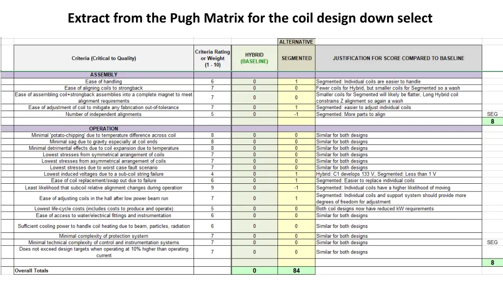
ENGINEERING CRITERIA Assembly Criteria The segmented coil design is less technically complex • Handling and assembly should be easier • However, final alignment may require more effort due to having to align more separate elements The segmented design should be more straightforward to assemble thereby reducing risk. Operation Criteria Both designs are very similar with regards to operation – i.e. forces, stresses, thermal growth are comparable Although the segmented design may be more prone to changes in alignment during operation, any misalignment can be assessed and addressed more easily than for the hybrid. The segmented design should be more straightforward to align for operation
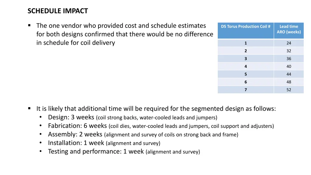
SCHEDULE IMPACT The one vendor who provided cost and schedule estimates for both designs confirmed that there would be no difference in schedule for coil delivery DS Torus Production Coil # Lead time ARO (weeks) 1 24 2 32 3 36 4 40 5 44 6 48 7 52 It is likely that additional time will be required for the segmented design as follows: • Design: 3 weeks (coil strong backs, water-cooled leads and jumpers) • Fabrication: 6 weeks (coil dies, water-cooled leads and jumpers, coil support and adjusters) • Assembly: 2 weeks (alignment and survey of coils on strong back and frame) • Installation: 1 week (alignment and survey) • Testing and performance: 1 week (alignment and survey)
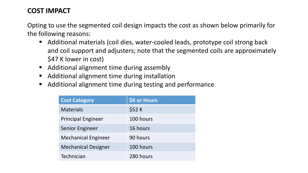
COST IMPACT Opting to use the segmented coil design impacts the cost as shown below primarily for the following reasons: Additional materials (coil dies, water-cooled leads, prototype coil strong back and coil support and adjusters; note that the segmented coils are approximately $47 K lower in cost) Additional alignment time during assembly Additional alignment time during installation Additional alignment time during testing and performance Cost Category $K or Hours Materials $52 K Principal Engineer 100 hours Senior Engineer 16 hours Mechanical Engineer 90 hours Mechanical Designer 100 hours Technician 280 hours
SUMMARY AND CONCLUSION The result of the Pugh matrix analysis is +84 in favor of the segmented option. Given that the weights can be somewhat subjective, the result was checked with equally weighted criteria, and the result is still in +17 favor of the segmented option. The results of implementing a finer field map to understand the relatively small differences between the hybrid and segmented are unlikely to change this decision. Therefore it is the recommendation of the Spectrometer Group that the MOLLER experiment move forward conditionally with a segmented configuration as the new baseline design for the spectrometer.
Extract from the Pugh Matrix for the coil design down select
Extract from the Pugh Matrix for the coil design down select
Extract from the Pugh Matrix for the coil design down select
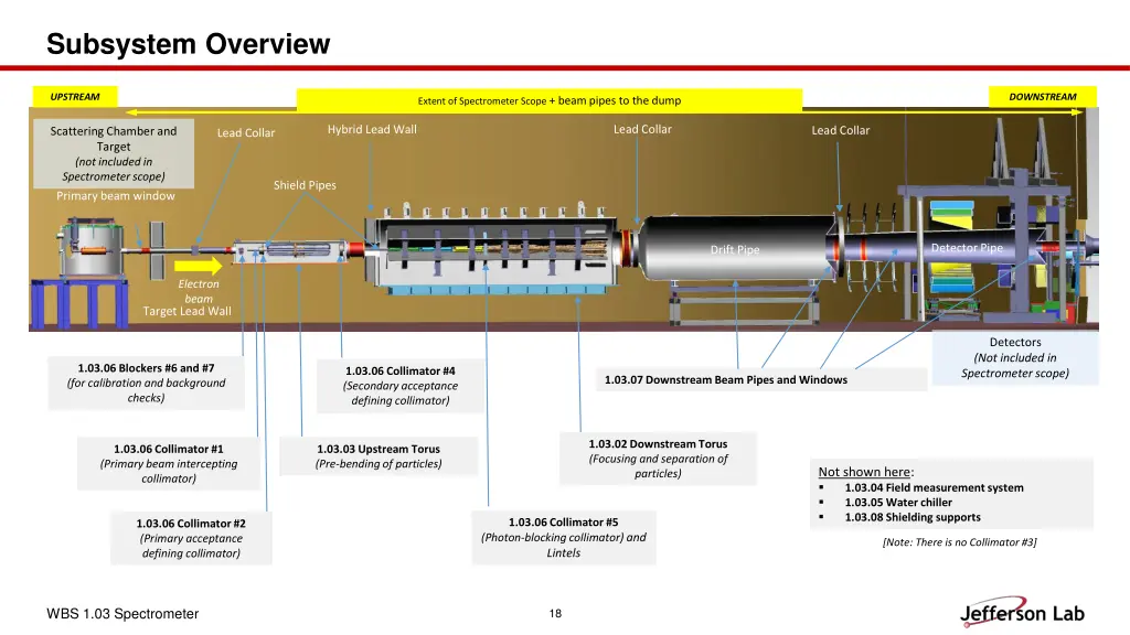
Subsystem Overview UPSTREAM DOWNSTREAM Extent of Spectrometer Scope + beam pipes to the dump Lead Collar Hybrid Lead Wall Lead Collar Scattering Chamber and Target (not included in Spectrometer scope) Primary beam window Lead Collar Shield Pipes Drift Pipe Detector Pipe Drift Pipe Electron beam Target Lead Wall Detectors (Not included in Spectrometer scope) 1.03.06 Blockers #6 and #7 (for calibration and background checks) 1.03.06 Collimator #4 (Secondary acceptance defining collimator) 1.03.07 Downstream Beam Pipes and Windows 1.03.02 Downstream Torus (Focusing and separation of particles) 1.03.06 Collimator #1 (Primary beam intercepting collimator) 1.03.03 Upstream Torus (Pre-bending of particles) Not shown here: 1.03.04 Field measurement system 1.03.05 Water chiller 1.03.08 Shielding supports 1.03.06 Collimator #5 (Photon-blocking collimator) and Lintels 1.03.06 Collimator #2 (Primary acceptance defining collimator) [Note: There is no Collimator #3] WBS 1.03 Spectrometer 18
BACKUP – Coil Hydraulic and Electrical Design O:\Magnet_Design_Tools\Magnet Projects\MOLLER - Hall A\6. Engineering Calculations-Analyses-Simulations\Mechanical\Coil DP calcs Filename: CDT 110percent - Sept 2020 100psi w_KPP Seg SC 4.xls Worksheet: Release Sheet_V2
Ver y good </ = 15 25 12 Desi gn Goal OK </ = 20 35 15 UPSTREAM Too Hi gh > 30 45 20 Hi gh</ = 30 45 20 Cur r ent densi t y Tem per at ur e r i se W at er vel oci t y Upstream Torus v2-6b Goal DP Total NI Number of turns LUVATA Conductor # Conductor width Conductor width Conductor hole dia Insulated Coil Clearance to envelope Current Density Temperature rise Water velocity Water Pressure Drop Subcoil String flow rate Voltage Subcoil String (PS voltage) Current Subcoil String (PS current) Power Subcoil String (PS power) V2- U1 Upstream Torus v2-6c Goal DP Total NI Number of turns LUVATA Conductor # Conductor width Conductor width Conductor hole dia Insulated Coil Clearance to envelope Current Density Temperature rise Water velocity Water Pressure Drop Subcoil String flow rate Voltage Subcoil String (PS voltage) Current Subcoil String (PS current) Power Subcoil String (PS power) 100% 100 5357. 5 100% 100 5357. 5 5 6 6842 6842 W H d C mm mm mm mm A/mm2 C ft/sec psi gpm V A kW 9 9 W H d C mm mm mm mm A/mm2 C ft/sec psi gpm V A kW 9 9 5. 7 1. 7 5. 7 1. 7 19.6 24.1 11.1 16.3 22.1 10.0 100. 0 DT V DP F V I P DT V DP F V I P 99. 9 9. 6 54. 4 8. 7 54. 2 892. 9 48. 4 1071. 5 58. 3
Ver y good </ = 15 25 12 Desi gn Goal OK </ = 20 35 15 Too Hi gh > 30 45 20 Hi gh</ = 30 45 20 HYBRID DS Cur r ent densi t y Tem per at ur e r i se W at er vel oci t y Hybrid SC1(1.02) Goal DP Total NI Number of turns LUVATA Conductor # Conductor width Conductor width Conductor hole dia Insulated Coil Clearance to envelope Current Density Temperature rise Water velocity Water Pressure Drop Subcoil String flow rate Voltage Subcoil String (PS voltage) Current Subcoil String (PS current) Power Subcoil String (PS power) Hybrid SC2 (1.02) Goal DP Total NI Number of turns LUVATA Conductor # Conductor width Conductor width Conductor hole dia Insulated Coil Clearance to envelope Current Density Temperature rise Water velocity Water Pressure Drop Subcoil String flow rate Voltage Subcoil String (PS voltage) Current Subcoil String (PS current) Power Subcoil String (PS power) 100% 100 7752 100% 100 2850 4 2 10000 8449 W H d C mm mm mm mm A/mm C ft/sec psi gpm V A kW 13 13 W H d C mm mm mm mm A/mm C ft/sec psi gpm V A kW 13 13 8. 5 4. 2 6 15. 5 17.4 19.4 12.7 100. 0 48. 6 123. 3 1938. 0 239. 0 10.2 16.5 11.0 100. 0 10. 5 30. 8 1425. 0 43. 9 DT V DP F V I P DT V DP F V I P
Ver y good </ = 15 25 12 Desi gn Goal OK </ = 20 35 15 Too Hi gh > 30 45 20 Hi gh</ = 30 45 20 HYBRID DS Cur r ent densi t y Tem per at ur e r i se W at er vel oci t y Hybrid SC3 (1.02) Goal DP Total NI Number of turns LUVATA Conductor # Conductor width Conductor width Conductor hole dia Insulated Coil Clearance to envelope Current Density Temperature rise Water velocity Water Pressure Drop Subcoil String flow rate Voltage Subcoil String (PS voltage) Current Subcoil String (PS current) Power Subcoil String (PS power) Hybrid SC4 (1.02) Goal DP Total NI Number of turns LUVATA Conductor # Conductor width Conductor width Conductor hole dia Insulated Coil Clearance to envelope Current Density Temperature rise Water velocity Water Pressure Drop Subcoil String flow rate Voltage Subcoil String (PS voltage) Current Subcoil String (PS current) Power Subcoil String (PS power) 100% 100 6260 100% 100 12300 4 10 8185 6819 W H d C mm mm mm mm A/mm C ft/sec psi gpm V A kW 13 13 W H d C mm mm mm mm A/mm C ft/sec psi gpm V A kW 13 13 10 9 25. 6 5. 7 15.0 20.6 10.6 100. 0 22. 8 75. 9 1565. 0 118. 8 13.9 11.8 10.9 100. 1 57. 9 140. 5 1230. 0 172. 9 DT V DP F V I P DT V DP F V I P
Ver y good </ = 15 25 12 Desi gn Goal OK </ = 20 35 15 Too Hi gh > 30 45 20 Hi gh</ = 30 45 20 SEGMENTED DS Cur r ent densi t y Tem per at ur e r i se W at er vel oci t y Segmented 1 (1.03) Goal DP Total NI Number of turns LUVATA Conductor # Conductor width Conductor width Conductor hole dia Insulated Coil Clearance to envelope Current Density Temperature rise Water velocity Water Pressure Drop Subcoil String flow rate Voltage Subcoil String (PS voltage) Current Subcoil String (PS current) Power Subcoil String (PS power) Segmented 2(1.03) Goal DP Total NI Number of turns LUVATA Conductor # Conductor width Conductor width Conductor hole dia Insulated Coil Clearance to envelope Current Density Temperature rise Water velocity Water Pressure Drop Subcoil String flow rate Voltage Subcoil String (PS voltage) Current Subcoil String (PS current) Power Subcoil String (PS power) 100% 100 8914. 8 100% 100 12192. 3 4 6 7034 12. 7 12. 7 4. 5 4. 1 8426 W H d C mm mm mm mm A/mm C ft/sec psi gpm V A kW 14 14 W H d C mm mm mm mm A/mm C ft/sec psi gpm V A kW 6 14. 5 12.2 14.8 13.0 15.4 23.2 13.9 DT V DP F V I P DT V DP F V I P 98. 8 12. 4 22. 9 98. 9 7. 5 19. 7 2032. 1 46. 6 2228. 7 43. 8 Segmented 3 (1.03) Goal DP Total NI 100% 100 19391. 3 8 LUVATA Conductor # Conductor width Conductor width Conductor hole dia Insulated Coil Clearance to envelope Current Density Temperature rise Water velocity Water Pressure Drop Subcoil String flow rate Voltage Subcoil String (PS voltage) Current Subcoil String (PS current) Power Subcoil String (PS power) 8151 W H d C mm mm mm mm A/mm C ft/sec psi gpm V A kW 15 15 7 23. 6 13.1 20.0 12.2 DT V DP F V I P 98. 9 15. 8 33. 1 2423. 9 80. 3
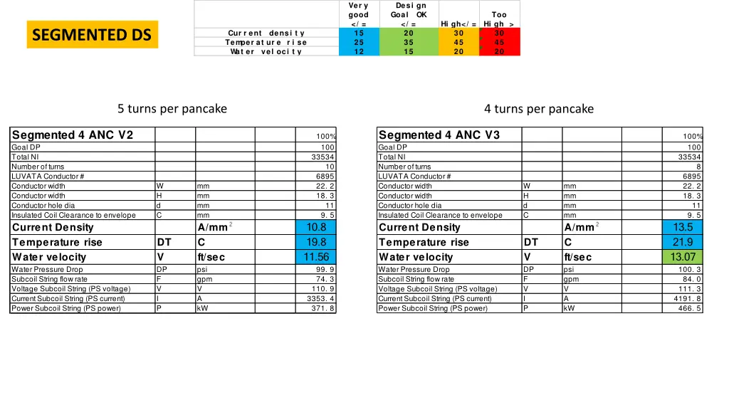
Ver y good </ = 15 25 12 Desi gn Goal OK </ = 20 35 15 Too Hi gh > 30 45 20 Hi gh</ = 30 45 20 SEGMENTED DS Cur r ent densi t y Tem per at ur e r i se W at er vel oci t y 5 turns per pancake 4 turns per pancake Segmented 4 ANC V3 Goal DP Total NI Number of turns LUVATA Conductor # Conductor width Conductor width Conductor hole dia Insulated Coil Clearance to envelope Current Density Temperature rise Water velocity Water Pressure Drop Subcoil String flow rate Voltage Subcoil String (PS voltage) Current Subcoil String (PS current) Power Subcoil String (PS power) Segmented 4 ANC V2 Goal DP Total NI Number of turns LUVATA Conductor # Conductor width Conductor width Conductor hole dia Insulated Coil Clearance to envelope Current Density Temperature rise Water velocity Water Pressure Drop Subcoil String flow rate Voltage Subcoil String (PS voltage) Current Subcoil String (PS current) Power Subcoil String (PS power) 100% 100 33534 100% 100 33534 10 8 6895 22. 2 18. 3 6895 22. 2 18. 3 W H d C mm mm mm mm A/mm C ft/sec psi gpm V A kW W H d C mm mm mm mm A/mm C ft/sec psi gpm V A kW 11 11 9. 5 9. 5 10.8 19.8 11.56 13.5 21.9 13.07 100. 3 84. 0 111. 3 4191. 8 466. 5 DT V DP F V I P DT V DP F V I P 99. 9 74. 3 110. 9 3353. 4 371. 8
BACKUP – Clearances to Particle Envelopes O:\Magnet_Design_Tools\Magnet Projects\MOLLER - Hall A\5. Preliminary Drawings - uncontrolled\Beamline Cad\ENVELOPE CLEARANCES Filename: COIL CLEARANCES 2_RRW_dk.xlsx Worksheet: Nov 2020
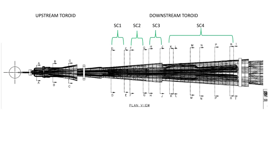
UPSTREAM TOROID DOWNSTREAM TOROID SC1 SC2 SC3 SC4
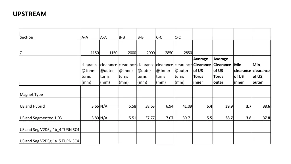
UPSTREAM Section A-A A-A B-B B-B C-C C-C Z 1150 1150 2000 2000 2850 2850 Average Clearance of US Torus inner Average Clearance of US Torus outer clearance @ inner turns (mm) clearance @outer turns (mm) clearance @ inner turns (mm) clearance @outer turns (mm) clearance @ inner turns (mm) clearance @outer turns (mm) Min clearance of US inner Min clearance of US outer Magnet Type US and Hybrid 3.66 N/A 5.58 38.63 6.94 41.09 5.4 39.9 3.7 38.6 US and Segmented 1.03 3.80 N/A 5.51 37.77 7.07 39.71 5.5 38.7 3.8 37.8 US and Seg V2DSg.1b_4 TURN SC4 US and Seg V2DSg.1a_5 TURN SC4
DOWNSTREAM – SC1 Section D-D D-D E-E E-E Z 5100 5100 5800 5800 clearance @ inner turns (mm) clearance @outer turns (mm) clearance @ inner turns (mm) clearance @outer turns (mm) Average Clearance of SC1 inner Average Clearance of SC1 outer Min clearance of SC1 inner Min clearance of SC1 outer Magnet Type US and Hybrid 2.78 18.56 3.88 19.98 3.3 19.3 2.8 18.6 US and Segmented 1.03 2.79 19.78 3.88 21.5 3.3 20.6 2.8 19.8 US and Seg V2DSg.1b_4 TURN SC4 US and Seg V2DSg.1a_5 TURN SC4

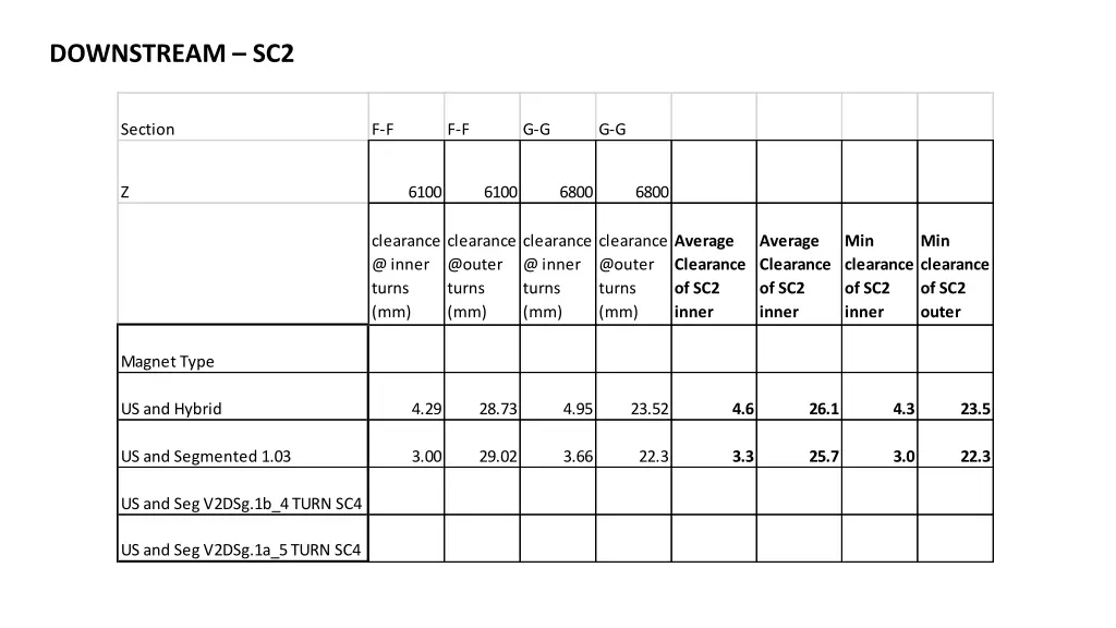
DOWNSTREAM – SC2 Section F-F F-F G-G G-G Z 6100 6100 6800 6800 clearance @ inner turns (mm) clearance @outer turns (mm) clearance @ inner turns (mm) clearance @outer turns (mm) Average Clearance of SC2 inner Average Clearance of SC2 inner Min clearance of SC2 inner Min clearance of SC2 outer Magnet Type US and Hybrid 4.29 28.73 4.95 23.52 4.6 26.1 4.3 23.5 US and Segmented 1.03 3.00 29.02 3.66 22.3 3.3 25.7 3.0 22.3 US and Seg V2DSg.1b_4 TURN SC4 US and Seg V2DSg.1a_5 TURN SC4
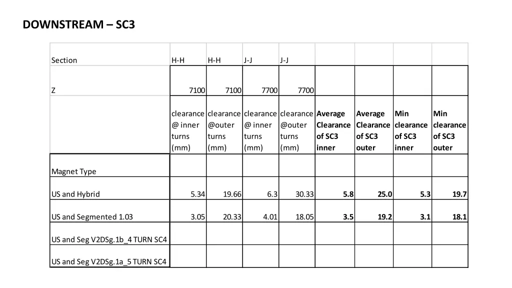
DOWNSTREAM – SC3 Section H-H H-H J-J J-J Z 7100 7100 7700 7700 clearance @ inner turns (mm) clearance @outer turns (mm) clearance @ inner turns (mm) clearance @outer turns (mm) Average Clearance of SC3 inner Average Clearance of SC3 outer Min clearance of SC3 inner Min clearance of SC3 outer Magnet Type US and Hybrid 5.34 19.66 6.3 30.33 5.8 25.0 5.3 19.7 US and Segmented 1.03 3.05 20.33 4.01 18.05 3.5 19.2 3.1 18.1 US and Seg V2DSg.1b_4 TURN SC4 US and Seg V2DSg.1a_5 TURN SC4
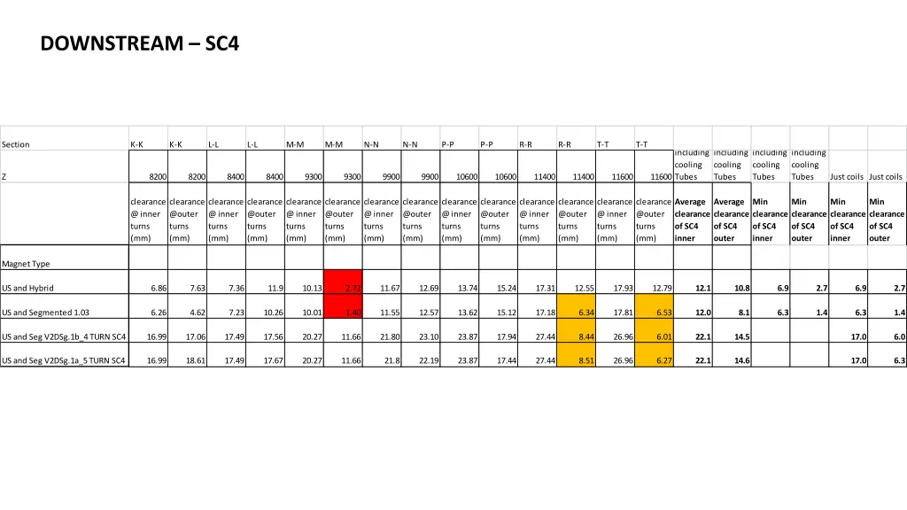
DOWNSTREAM – SC4 Section K-K K-K L-L L-L M-M M-M N-N N-N P-P P-P R-R R-R T-T T-T including cooling Tubes including cooling Tubes including cooling Tubes including cooling Tubes Z 8200 8200 8400 8400 9300 9300 9900 9900 10600 10600 11400 11400 11600 11600 Just coils Just coils clearance @ inner turns (mm) clearance @outer turns (mm) clearance @ inner turns (mm) clearance @outer turns (mm) clearance @ inner turns (mm) clearance @outer turns (mm) clearance @ inner turns (mm) clearance @outer turns (mm) clearance @ inner turns (mm) clearance @outer turns (mm) clearance @ inner turns (mm) clearance @outer turns (mm) clearance @ inner turns (mm) clearance @outer turns (mm) Average clearance of SC4 inner Average clearance of SC4 outer Min clearance of SC4 inner Min clearance of SC4 outer Min clearance of SC4 inner Min clearance of SC4 outer Magnet Type US and Hybrid 6.86 7.63 7.36 11.9 10.13 2.72 11.67 12.69 13.74 15.24 17.31 12.55 17.93 12.79 12.1 10.8 6.9 2.7 6.9 2.7 US and Segmented 1.03 6.26 4.62 7.23 10.26 10.01 1.40 11.55 12.57 13.62 15.12 17.18 6.34 17.81 6.53 12.0 8.1 6.3 1.4 6.3 1.4 US and Seg V2DSg.1b_4 TURN SC4 16.99 17.06 17.49 17.56 20.27 11.66 21.80 23.10 23.87 17.94 27.44 8.44 26.96 6.01 22.1 14.5 17.0 6.0 US and Seg V2DSg.1a_5 TURN SC4 16.99 18.61 17.49 17.67 20.27 11.66 21.8 22.19 23.87 17.44 27.44 8.51 26.96 6.27 22.1 14.6 17.0 6.3