Download
1 / 29
300 likes | 454 Views
TRANSMISSION MEDIA. SYSC 4700 Telecommunications Engineering David Falconer and Halim Yanikomeroglu Carleton University. 06 February 2014. Transmission Media. Objectives To learn some basic vocabulary: e.g. channels, circuits, trunks, dB, dBm , dBw .

E N D
TRANSMISSION MEDIA SYSC 4700 Telecommunications Engineering David Falconer and Halim Yanikomeroglu Carleton University 06 February 2014
Transmission Media Objectives • To learn some basic vocabulary: e.g. channels, circuits, trunks, dB, dBm, dBw. • To have an idea of the relative bandwidths of some common signals. • Link budget. • To learn the basic characteristics, advantages and limitations of common transmission media.
Channels, Circuits, Trunks • Channel: refers to the medium (such as copper wire, radio, coaxial cable, satellite, or optical fiber) used to convey information from a transmitter to a receiver. • Circuit: the physical path between two terminals over which one- or two-way communication is provided. • Trunk: a single transmission channel between two switching centers or nodes. • Circuits and trunks are equipped with signaling and other terminating equipment.
Typical Bandwidths and Bit Rates Required Analog Voice • POTS (plain old telephone system): 300 to 3400 Hz • AM broadcasting: 10 KHz • FM broadcasting: 200 KHz Digital Voice • PCM DS0: 64 Kb/s • compressed voice: 8, 16, or 32 Kb/s • CD: 1.4112 Mb/s (2-channel, 16-bit PCM sampled at 44.1 KHz) MP3 (MPEG-1 Audio Layer 3): 96 kb/s (FM quality) 192 kb/s (DAB quality)
Typical Bandwidths and Bit Rates Required • Analog TV video: 6 MHz • Digital compressed TV video: ~1.5 MHz (~1 Mb/s) • HDTV: 8-15 Mb/s (with MPEG-4 compression) • Video teleconferencing: 384 Kb/s. • Dial-up PC modem: v.34: 28.2 kb/s; v.90: 56 kb/s • High speed data: at least several Mb/s • Blu-ray: 40 Mb/s (max) • IEEE 802.11a, .11g: 54 Mb/s (shared peak rate) • 3G Cellular: 2-40 Mb/s (shared peak rate) • 4G Cellular: 100 Mb/s – mobile (shared peak rate) 1 Gb/s – nomadic (shared peak rate)
Four-wire trunk Subscriber loop: Two-wire twisted copper pair. Multiplexing and switching node Two Wire and Four Wire Circuits Two-wire circuit: A full-duplex communications circuit that utilizes only two metallic conductors, e.g., a single twisted pair. Four-wire circuit: A two-way circuit using two paths so arranged that the respective signals are transmitted in one direction only by one path and in the other direction by the other path. Note: The four-wire circuit gets its name from the fact that, historically, two conductors were used in each of two directions for full-duplex operation. [Wikipedia] A two-wire circuit is characterized by supporting transmission in two directions simultaneously, as opposed to four-wire circuits, which have separate pairs for transmit and receive. In either case they are twisted pairs. Telephone lines are almost all two wire, while trunks and switching are almost entirely four wire. A four-wire circuit is a two-way circuit using two paths so arranged that the respective signals are transmitted in one direction only by one path and in the other direction by the other path. Late in the 20th century, almost all connections between telephone exchanges were four-wire circuits, while conventional phone lines into residences and businesses were two-wire circuits.
Key Points • Nowadays four wire circuits are used for all circuits except for most subscriber loops. • Four wire circuit can be 4 physical wires or a pair of frequency channels or time slots (depending on transmission medium). • Four wire digital transmission is prevalent today. • Media: each type of transmission medium is advantageous in a particular situation.
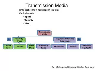
TRANSMISSION MEDIA Subscriber loop: Twisted copper pair cable. Twisted copper pair. Coaxial cable Optical fibre. Optical fibre Radio Microwave radio Satellite Multiplexing and switching node
MULTIPLEX/SWITCH NODE TX RX MUX DEMUX To/from other trunks SWITCH To/from subscribers
Decibel Unit • A power ratio X/Y, expressed in decibels (dB) is 10 log(X/Y) = 10logX-10logY (note: X and Y must be proportional to power) • dBm means power relative to 1 milliwatt; i.e. 10log(power in milliwatts) • dBw means power relative to 1 watt; i.e., 10log(power in watts). • 0 dBw (meaning 1 watt) = 30 dBm.
Link Budgets Transmitter Channel Receiver Noise Gain Gt dB Gain Gr dB Attenuation L dB Received power in dBw: Pr = Pt + Gt – L + Gr(all quantities in dB scale) Received power in watts: Pr = Pt Gt Gr /L (all quantities in linear scale) Noise power in dBw: N = - 228.6 + 10log10(273 + C°) + 10log10(B) +F where °C = temp. in degrees centigrade; B = signal bandwidth in Hz; F=noise figure in dB Noise power in watts: k T B F (all quantities in linear scale) where k = 1.38 x 10⁻²³ (Boltzmann’s constant); T = 273+°C Signal to noise ratio (SNR) in dB = Pr - N SNR in linear: Pr/N Note: Attenuation L usually depends on distance and frequency. Link budget: Determine minimum transmit power etc. which satisfy these equations and give a required minimum SNR. Transmit power Pt dBw
VF (Voice Frequency) Cable - Paired Metallic Conductors • Aerial (on poles): exposed to damage and environment • Buried: more expensive to install; trouble locating • Pro • Compact, fairly high capacity (up to 1000 pairs per cable) - but low compared to coax and optical fiber • Quality controlled in factory • Con • High loss • Subject to crosstalk interference from neighbouring pairs in same cable
Coaxial Cable • Aerial or buried • Large bandwidth (~1000 MHz), high capacity • Self shielding • Relatively expensive
Attenuation (dB\km.) [Fig. 7.20 from “Telecommunication System Engineering” 2nd ed., by R.L. Freeman, Wiley, Ny. 1989] Frequency (MHz) Attenuation of 0.375 in. coax cable
Summary • Twisted copper pairs used in telephone subscriber loop plant: • Attenuation and usable bandwidth depends on length and thickness. • Many pairs in a cable in close proximity - subject to crosstalk interference. • Coax used in CATV plant: • Much lower attenuation and much higher usable bandwidth for same length. • Insulated - little or no interference. • More expensive and bulky, but can carry more payload.
Radio • Microwave Line of Sight (LOS) • Cellular, WLAN, WiMax, sensor, ad hoc, PAN • Dispatch, paging • Pro • Low real estate and installation cost (don’t need to install wires or fibers to every possible customer), good coverage • Mobility • Con • Subject to interference and propagation disturbances • Security, privacy a concern
Line of Sight (LOS) Radio Propagation Free space path loss in linear scale: (4πd/λ)^2 Free space path loss (FSPL) in dB =10 log10 (input power/output power) = -147.6+20 log10 f + 20 log10 d where frequency f is in Hertz and distance d is in metres.
Non-Line of Sight Radio Propagation Diffraction Reflection Impulse response: Frequency response: Obstruction (shadowing) Scattering, diffraction “Multipath”
Sample Link Budget for a Radio Link Transmitter Receiver Distance d Noise Given: Signal centre frequency f = 4 GHz Distance d = 20 km. Total antenna gains and cable losses = Gt + Gr= 24 dB Bandwidth = B = 10 MHz Noise figure = 10 dB; Temp = 17°C Required SNR = 20 dB Free space path loss (FSPL) in dB = -147.6 + 20 log10 f + 20 log10 d = 130.4 dB [f is in Hz and d is in m.] Noise power in dBw = - 228.6 + 10log10(273 + C°) + 10log10(B) +F = -124 dBwRequired received power in dBw = SNR + Noise Power = 20 – 124 = -104 dBw Required transmit power = Required received power + Path Loss - Gains = -104 + 130.4 - 24 = 2.4 dBw = 1.74 watts
Shadowing • Path loss variation due to obstructions, combined with distance • Path loss (dB) =avg. path loss+random path loss Avg. path loss Path Loss (dB) Measured path loss Free space path loss Distance (log scale)
Fiber Optic Cable • Most long-haul trunks in Canada and U.S. are now carried on optical fiber. • Huge capacity. • High installation cost (but low cost per circuit in large capacity systems). • Immune to electromagnetic interference. • Low attenuation. • Long life. • Small size - makes better use of cable ducts. • Excellent for digital signals.
Satellites • Microwave frequency repeaters in geostationary orbits (~40,000 km.) • Large coverage; e.g., all of Canada. • Large capacity, high quality. • Extensively used by TV networks. • Capacity shared by multiple access. • Excellent for providing fixed or mobile coverage in remote areas, across oceans (although fiber is taking over).
Low Earth Orbit (LEO) • 500km-1500km from earth low delay • Non-stationary, satellites rise and fall (orbit time ~ 90 minutes) • Smaller satellites with less transponders (~100 kg to 500 kg) • Closer lower launch costs and requirements • Closer smaller antennas, lower power requirements (ground terminals, satellite) • Need many, many satellites to provide global, uninterrupted coverage (example: original Teledesic needed 800! Skybridge requires 80) • Hand-off required, complex signal routing needed • Geo-stationary Earth Orbit (GEO) • 30,000 km - 40,000 km from earth larger delay • Appear stationary to earth observer (Clarke’s orbit!) • Larger satellites with many transponders (~ 1 to 20 tons!) • Further higher launch costs and requirements • Further larger antennas, Kwatts of power requirements • Theoretically, can cover earth with 3 satellites • No-hand-off needed, simpler signal routing • Medium Earth Orbit (MEO) • 4,000-12,000 km from earth Orbits (LEO, GEO, MEO)
Satellite Types • Bent Pipe Satellites • Simple Repeaters in the sky • Receive a signal on frequency F1, amplify it, transmit it on frequency F2 • Almost all of today’s commercial satellites are bent pipe • Regenerative Satellites • Deploy on-board processing (OBP) • Receive signals, demodulate them, make intelligent decision on where to send them, modulate them and transmit them • Restricted to a few military satellites, they are becoming the preferred type of the next generation communication satellites • Iridium is a Regenerative satellite