Download
1 / 32
380 likes | 722 Views
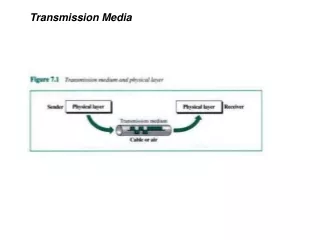
University of Calgary – CPSC 441. Transmission Media. The Physical Layer. Transfer information over a transmission medium Converts bit streams into electrical or optical signals (and back)

E N D
University of Calgary – CPSC 441 Transmission Media
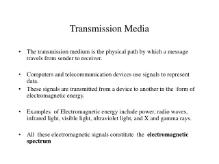
The Physical Layer • Transfer information over a transmission medium • Converts bit streams into electrical or optical signals (and back) • The signal propagates over the transmission medium at different speeds depending on the physical characteristics of the medium. • An electromagnetic wave propagates through vacuum at a speed of c=3*108m/s and at lower speeds in other materials.
Quality of Transmission Media • A good transmission medium should provide communication with good quality at long distance. • For voice communication, quality of communication is determined by the voice quality. • For data communication, however, the quality of communication is mainly determined by the effective data rate of communication.
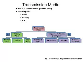
Classes of Transmission Media • Conducted or guided media • use a conductor such as a wire or a fiber optic cable to move the signal from sender to receiver • Wireless or unguided media • use radio waves of different frequencies and do not need a wire or cable conductor to transmit signals
Design Factors • Bandwidth: All other factors remaining constant, the greater the band-width of a signal, the higher the data rate that can be achieved. • Transmission impairments:Limit the distance a signal can travel. • Interference: Competing signals in overlapping frequency bands can distort or wipe out a signal. • Number of receivers:Each attachment introduces some attenuation and distortion, limiting distance and/or data rate.
Guided Transmission Media • Transmission capacity depends on the distance and on whether the medium is point-to-point or multipoint • Examples • twisted pair wires • coaxial cables • optical fiber
Twisted Pair • Consists of two insulated copper wiresarranged in a regular spiral pattern to minimize the electromagnetic interference between adjacent pairs • Low frequency transmission medium (traditional phone wires, 10 or 100 Mbps Ethernet, enhanced Cat 5 and 6 can handle gigabit+ Ethernet)
Types of Twisted Pair • UTP (Unshielded Twisted Pair) • Each wire is insulated with plastic wrap, but the pair is encased in an outer covering • Category 3 UTP (16MHz Bandwidth; 10BASE-T/100BASE-T4) • Category 5 UTP (100MHz Bandwidth; 100BASE-T/1GBASE-T with Cat 5e) • More tightly twisted than Category 3 cables • Four pairs of copper wire • Category 6 UTP (250MHz Bandwidth; 10GBASE-T up to 55 meters) • STP (Shielded Twisted Pair) • The pair is wrapped with metallic foil or braid to insulate the pair from electromagnetic interference • Category 6a STP (500MHz Bandwidth; 10GBASE-T up to 100 meters)
Twisted Pair: Pros and Cons • Advantages: • Inexpensive and readily available • Flexible and light weight • Easy to work with and install • Disadvantages: • Susceptibility to interference and noise • Attenuation problem • For analog, repeaters needed every 5-6km • For digital, repeaters needed every 2-3km • Relatively low bandwidth
Coaxial Cable • Also known as Coax • Used for cable television, LANs, telephony • Has an inner conductor surrounded by a braided mesh • Both conductors share a common center axial, hence the term “co-axial” outer jacket (polyethylene) shield(braided wire) insulating material copper or aluminum conductor
Coaxial Cable Characteristics • Higher bandwidth • 400 to 600Mhz • up to 10,800 voice conversations • Can be tapped easily • Less susceptible to interference than twisted pair • High attenuation rate makes it expensive over long distance (needs amplifiers every few km)
plastic jacket glass or plastic cladding fiber core Fiber Optic Cable • Glass fiber carrying light pulses, each pulse a bit • Greater capacity high-speed point-to-point transmission (10’s-100’s Gbps) • Smaller size and lighter weight • Lower attenuation (fewer repeaters) • Low error rate (immune to electromagnetic noise) • Hard to tap
Fiber Optic Types • Multimode step-index fiber • The reflective walls of the fiber move the light pulses to the receiver • Multimode graded-index fiber • Acts to refract the light toward the center of the fiber by variations in the density • Single mode fiber • the light is guided down the center of an extremely narrow core
Wireless (Unguided Media) Radio link types: Common Characteristics Signal carried in electromagnetic spectrum No physical “wire” Multidirectional Propagation environment effects: reflection obstruction by objects interference • Terrestrial microwave • up to 45 Mbps channels • LAN (e.g., WiFi) • 11 Mbps, 54 Mbps • Wide-area (e.g., cellular) • 3G: ~ 1 Mbps • LTE: ~ 300 (DL), 75 (UL) Mbps • Satellite • Kbps to 45 Mbps channel (or multiple smaller channels) • 270 msec end-end delay • geosynchronous versus low altitude
Residential access networks Institutional access networks (school, company) Mobile access networks Questions to ask: bandwidth (bits per second) of access network? shared or dedicated? Access Networks and Physical Media
Dial-up Modem central office telephone network Internet homedial-up modem ISPmodem (e.g., AOL) home PC • Uses existing telephony infrastructure • Home is connected to central office • up to 56Kbps direct access to router (often less) • Can’t surf and phone at same time: not “always on”
telephone network Digital Subscriber Line (DSL) Existing phone line:0-4KHz phone; 4-50KHz upstream data; 50KHz-1MHz downstream data Internet home phone DSLAM splitter DSL modem central office home PC • Also uses existing telephone infrastructure • up to 1 Mbps upstream • up to 8 Mbps downstream • dedicated physical line to telephone central office
DOCSIS • Data Over Cable Service Interface Specification (DOCSIS) is an international standard for data communication via existing cable TV (CATV) systems utilizing coax cable • Build on HFC: Hybrid fiber-coaxial • Fiber optic network extends from cable operator headend to the neighborhood coaxial cable node • The coaxial cable node (and router) serves 25 – 2000 homes • Homes share access to router, unlike DSL which has dedicated access • DOCSIS 3.1 uses orthogonal frequency division multiplexing (OFDM) subcarriers with 4096 quadrature amplitude modulation (QAM) in a 200MHz baseband block • Asymmetric division of bandwidth for upstream/downstream • Up to 1 Gbit/s upstream • Up to 10 Gbit/s downstream
Cable Network Architecture: Overview cable headend home cable distribution network (simplified) 25-200 homes (typically 500)
C O N T R O L D A T A D A T A V I D E O V I D E O V I D E O V I D E O V I D E O V I D E O 5 6 7 8 9 1 2 3 4 Channels Cable Network Architecture: Overview FDM (more shortly): cable headend home cable distribution network (simplified)
ONT ONT ONT Fiber to the Home opticalfibers Internet • Optical links from central office to the home • Two competing optical technologies: • Passive Optical network (PON) • Active Optical Network (PAN) • Much higher Internet rates; fiber also carries television and phone services opticalfiber OLT optical splitter central office
Data Encoding Techniques • Digital Data, Analog Signals [modem] • Digital Data, Digital Signals [wired LAN] • Analog Data, Digital Signals [codec] • Frequency Division Multiplexing (FDM) • Wave Division Multiplexing (WDM) [fiber] • Time Division Multiplexing (TDM) • Pulse Code Modulation (PCM) [T1] (digital transmission systems developed by Bell Labs) • Delta Modulation
Digital Data, Digital Signals[the technique used in a number of LANs] • Digital signal – is a sequence of discrete, discontinuous voltage pulses. • Bit duration : the time it takes for the transmitter to emit the bit. • Issues • Bit timing • Recovery from signal • Noise immunity
Binary Encoding • NRZ (non-return to zero) • NRZI (NRZ inverted) • Manchester (used by IEEE 802.3, 10 Mbps Ethernet)
Bits 0 0 1 0 1 1 1 1 0 1 0 0 0 0 1 0 NRZ Non-Return to Zero (NRZ) • Encode binary data onto signals • e.g., 0 as low signal and 1 as high signal • voltage does not return to zero between bits • known as Non-Return to Zero (NRZ)
sender’s clock receiver’s clock Problem: Consecutive 1s or 0s • Low signal (0) may be interpreted as no signal • High signal (1) leads to baseline wander • Unable to recover clock • sender’s and receiver’s clock have to be precisely synchronized • receiver resynchronizes on each signal transition • clock drift in long periods without transition
NRZI • Non-Return to Zero Inverted (NRZI) • Has a transition at a clock boundary if the bit being transmitted is “1” • Stay at current signal (maintain voltage level) to encode/ transmit a “zero” • Solves the problem of consecutive ones (shifts to 0s) • NRZI can have long series of zeros , still unable to recover clock
Manchester • Manchester (in IEEE 802.3 – 10 Mbps Ethernet) • Split cycle into two parts • Send high--low for “1”, low--high for “0” • Transmit XOR of NRZ encoded data and the clock • Clock signal can be recovered from the encoded data. • Only 50% efficient (1/2 bit per transition): double the transmission rate.
Bits 0 0 1 0 1 1 1 1 0 1 0 0 0 0 1 0 NRZ Clock Manchester NRZI Different Encoding Schemes
References • CPSC 441 Chapter 1 Slides 16-28 • http://en.wikipedia.org/wiki/File:NRZI_example.png • CS716 Advanced Computer Networks by Dr. Amir Qayyum • zlin.ba.ttu.edu/doc/ws7.ppt