Download
1 / 16
160 likes | 286 Views
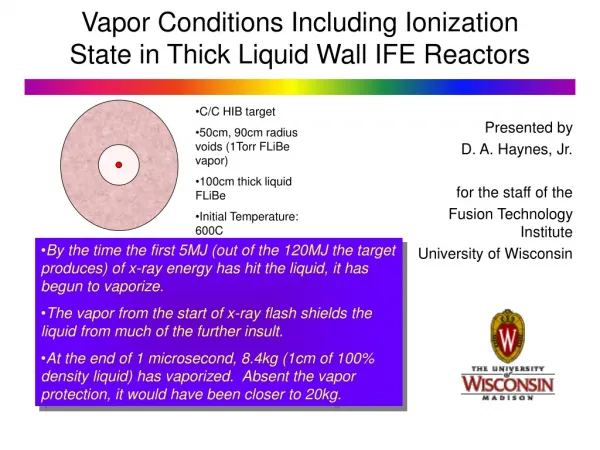
1. Concluding Sacrificial Liquid Film Activities 2. Starting Thick Liquid Wall Activities . A. R. Raffray, J. Pulsifer, M. Zaghloul University of California, San Diego ARIES-IFE Meeting University of Wisconsin April 22-23, 2002. Outline. • Thin liquid film - Condensation

E N D
1. Concluding Sacrificial Liquid Film Activities 2. Starting Thick Liquid Wall Activities A. R. Raffray, J. Pulsifer, M. Zaghloul University of California, San Diego ARIES-IFE Meeting University of Wisconsin April 22-23, 2002
Outline • Thin liquid film - Condensation - Aerosol source term - Documentation • Thick liquid wall - Key Issues - How to address them within ARIES
jevap Pg Tg Tf jcond Condensation Flux and Characteristic Time to Clear Chamber as a Function of Pb Vapor and Film Conditions - Characteristic time to clear chamber, tchar, based on condensation rates and Pb inventory for given conditions - For higher Pvap (>10 Pa for assumed conditions), tchar is independent of Pvap - For lower Pvap as condensation slows down, tchar increases substantially
Vapor Condensation Rate can be Affected by Presence of Non-Condensable Gas P Pg,i Pv,o Pg,o Pv,i Tv,o Tv,i d • When pressure of vapor is of the same order as that of non- condensable gas, overall pressure equilibrium results in local vapor and gas gradients and condensation becomes diffusion-limited jcond = condensation flux (kg/m2-s) Kv,g = binary mass transfer coefficient for diffusion of vapor and gas over diffusion length (m/s) rv = vapor density (kg/m3) Pg,lm = log mean pressure of non-condensable gas (Pa) Pv,o, Pv,i = vapor pressure in chamber and at interface (Pa)
Pb Vapor Diffusion Rate and Characteristic Time as a Function of Xe Gas Pressure for Different Pb Vapor Pressure Values • At higher Xe pressure, Pb diffusion rate in Xe limits the effective condensation rate and decreases rapidly with increasing concentration of Xe (non-condensable gas) • For the example considered the Xe pressure threshold for diffusion control is ~ 1.5 Pa for a Pb vapor pressure of 100 Pa and ~ 0.1 Pa for a Pb vapor pressure of 2 Pa Chamber size = 5 m Pb film temperature = 1000 K Pb vapor temperature = 2000 K
Energy Deposition & Transient Heat Transport x Induced Thermal- Spikes Fast Ions y z Mechanical Response Phase Transitions Slow Ions • Stresses and Strains and Hydrodynamic Motion • Fractures and Spall • Surface Vaporization • Heterogeneous Nucleation • Homogeneous Nucleation (Phase Explosion) Material Removal Processes Expansion, Cooling and Condensation Processes Leading to Aerosol Formation following High Energy Deposition Over Short Time Scale Surface Vaporization Liquid Film X-Rays Impulse Spall Fractures Impulse Phase Explosion Liquid/Vapor Mixture
Vaporization from Free Surface • Occurs continuously at liquid surface • Governed by the Hertz-Knudsen equation for flux of atoms e = vaporization coefficient, c = condensation coefficient, m = mass of evaporating atom, k = Boltzmann’s constant, Ps = saturation pressure Pv = pressure of vapor Tf = film temperature Tv = vapor temperature Ion-like heating rate Photon-like heating rate • Liquid-vapor phase boundary recedes with velocity: • For constant heating rate, g, and expression for saturation pressure as a function of temperature the following equation can be integrated to estimate fractional mass evaporated over the temperature rise. The results are shown for Pb. • Free surface vaporization is very high for heating rate corresponding to ion energy deposition • For much higher heating rate (photon-like) free surface vaporization does not have the time to occur and its effect is much reduced
Vaporization into Heterogeneous Nuclei • Occurs at or somewhat above boiling temperature, T0 • For heterogeneous nucleation, the vapor phase appears at perturbations in the liquid (impurities etc.) • From Matynyuk, the mass vaporized into heterogeneous nuclei per unit time is given by: Photon-like heating rate Ion-like heating rate v = density of vapor in the nucleus, Hv = enthalpy of vaporization per unit mass, 0 = density of saturated vapor at normal boiling temperature (T0) P0 is the external static pressure • Vaporization into Heterogeneous nuclei is dependent on the number of nuclei per unit mass but is very low for heating rate corresponding to ion energy deposition and even lower for photon-like energy deposition • The equation can be integrated over temperature for a given heating rate, g, and following some simplifying assumptions (Fucke and Seydel). The results are shown for Pb.
Phase Explosion (Explosive Boiling) (I) • Rapid boiling involving homogeneous nucleation both at and beneath the surface. • High heating rate Pvapor does not build up as fast and thus falls below Psat @ Tsurface superheating to a metastable liquid state limit of superheating is the limit of thermodynamic phase stability, the spinode (defined by P/v)T = 0) • A given metastable state can be achieved in two ways: a) by raising the temperature from the boiling point while keeping the pressure lower than the corresponding saturation values (e.g. high heating rate) b) by reducing the pressure from the saturated value while keeping the corresponding temperatures lower than the saturated values (e.g. rarefaction wave) • A metastable liquid has an excess free energy, so it decomposes explosively into liquid and vapor phases. - As T/Ttc increases past 0.9, Becker-Döhring theory of nucleation indicate an an avalanche-like and explosive growth of nucleation rate (by 20-30 orders of magnitude)
Phase Explosion (Explosive Boiling) (II) Volumetric Model with Phase Explosion from Photon Energy Deposition Esens = Energy density required for the material to reach the saturation temperature E ( 0.9 Ttc )= Energy density required heat the material to 0.9 Ttc Et = Total evaporation energy (= Esens + E Evaporation) • Liquid and vapor mixture evolved by phase explosion shown by shaded area (~0.5 mm for Pb with quality >~0.8; ~2.9 mm for Li) • Could be higher depending on behavior of 2-phase region behind • Very challenging to predict aerosol size and number from this
Upper Bound Estimate of Combination of Number of Droplets and Droplet Size as a Function of Evaporated Film Thickness • Suggest to do aerosol calculations for two case assuming a drop radius based on pressure and surface tension equilibrium: 1. Assume all liquid in 2-phase region in aerosol form 2. Assume all liquid in explosive ablation layer in aerosol form • Sensitivity analysis on droplet size
Proposed Outline of Thin Liquid Film Paper (I)(First draft to be written over next 3-4 months and to be published in FE&D) • DRAFT • 1. Introduction (R. Raffray) (~ 0.5 page) • 2. Example configuration (~ 0.5-1 page) (L. Waganer) • 3. Driver requirements (~ 2 pages) • - Heavy Ion beam (C. Olson, S. Yu) (~ 1 page) • - Laser (M. Tillack, J. Sethian) (~ 1 page) • 4. Target requirements (D. Goodin, R. Petzold) (~ 2 pages) • - Indirect drive • - Direct drive • 5. Film analysis (S. Abdel Khalik, M. Yoda) (~ 2-3 pages) • - Flowing film • - Continuous injection from the back (e.g. through porous media) • 6. Energy deposition (D. Haynes) (1-2 pages) • - Based on Pb vapor pressure and any additional chamber gas • - Other liquids (FLiBe?)
Proposed Outline of Thin Liquid Film Paper (II)(First draft to be written over next 3-4 months and to be published in FE&D) • 7. Chamber clearing (thermal and mass transfer analysis) • - Condensation scoping analysis (R. Raffray) (1 page) • - Source term for aerosol formation (A. Hassanein, D. Haynes) (2 pages) • - Aerosol analysis (P. Sharpe) (1 page) • 8. Design window (Raffray, others)(1 page) • - Aerosol size and concentrations • - Incorporate estimate based on conditions and driver and target requirements • 9. Radiological issues (L.El-Guebaly) (0.5 page) • - Choice of liquids • - Effect on overall waste disposal issues • 10. Safety issues (D. Petti, L. El-Guebaly) (0.5 page) • 11. Key remaining issues (R. Raffray, all) (0.5 page) • 12. Conclusions (R. Raffray, all) (0.5 page) • Total = ~ 17 journal pages
Schematic of a potential thick-liquid pocket, showing major pocket features. Porosity in liquid blanket Stationary grid of cylindrical jets Beam ports and solid shielding structure (same both sides) Venting path for target and ablation debris Heavy ion target Oscillating liquid jets Some Thoughts on Assessing the Thick Liquid Wall Option (I) Major issues tend to be design dependent; e.g. for HYLIFE Hydraulics • Jet formation to assure coverage while providing pocket for target explosion and channels for driver firing and target injection, and chamber clearing • This is is being addressed by an ongoing modeling and experimental fluid dynamics program - ARIES would not be able to provide much more in this area within the time frame and scope of the study Chamber clearing • Return chamber environment to a condition which allows successful target and driver propagation - Many issues similar to thin liquid wall option, including aerosol formation and condensation - Fluid dependent (analysis should be done for FLiBe and other fluids?)
Some Thoughts on Assessing the Thick Liquid Wall Option (II) Interface and integration issues • Areas where ARIES could best provide some insight, trade-offs and design windows • Demand on nozzle - Mechanical design of nozzle (moving parts) - Reliability for such demanding performance - Effect of malfunction - irradiation effect - out of phase oscillation - nozzle choking because of impurity in fluid - fluid chemistry control requirements - presence of debris and holhraum materials • Choice of fluid and structural materials - Shielding performance (what is the goal, class C???) - Lifetime of structural materials - Power cycle. Can it be optimized? - Poor thermal conductivity of FLiBE - ok for volumetric heat deposition - poor heat transfer leads to large HX or DT between primary and secondary fluids - Pressure drop and pumping power
Some Thoughts on Assessing the Thick Liquid Wall Option (III) Interface and integration issues • Adequate shielding for last focus magnet - Further analysis? • Specific target and driver requirements for thick liquid wall option - Vapor pressure of FLiBe (opening of pocket would create a pressure increase due to suction effect) - Aerosol formation (droplets) - Possible condensation of FLiBe in lines (effect on heavy ion beam) • Gaps required for driver and target - Possibility of bare wall seeing photons and ions in direct line of sight - effect of off-centered micro-explosion - consequences - would you a thin liquid film be needed? • Safety issues - e.g. possible accident scenarios