Liquid Chromatography 2
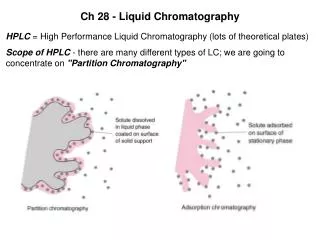
Liquid Chromatography 2. Lecture Date: April 14 th , 2008. Outline of Topics. UHPLC – ultra-high pressure liquid chromatography (also referred to as UPLC TM , as sold by Waters) Smaller particle packed columns Monolithic stationary phases: Dionex ProSwift TM Phenomenex Onyx TM 2D LC


Liquid Chromatography 2
E N D
Presentation Transcript
Liquid Chromatography 2 Lecture Date: April 14th, 2008
Outline of Topics • UHPLC – ultra-high pressure liquid chromatography (also referred to as UPLCTM, as sold by Waters) • Smaller particle packed columns • Monolithic stationary phases: • Dionex ProSwiftTM • Phenomenex OnyxTM • 2D LC • Micro-HPLC • Eksigent Technologies 8-channel HPLC • NanoStream 24 column HPLC • Other examples • Preparative and Simulated Moving Bed (SMB) LC
10 min 10 min 10 min Particle Size Evolution Late 1960’s 40µm pellicular non-porous coated 100-500 psi (7.1-35.5 bar) 1000 plates/meter 1m columns Early 1970’s 10µm Irregular micro-porous 1000-2500 psi (71-177 bar) 25,000 plates/meter 3.9 x 300mm Diagrams from Waters Inc. 1980’s to present day 3.5 - 5µm spherical micro-porous 1500-4000 psi (106.4-283.7 bar) 50,000 - 80,000 plates/meter 3.9 x 300mm J. R. Mazzeo, U. W. Neue, M. Kele, and R. S. Plumb, “Advancing LC Performance with smaller particles and higher pressure”, Anal. Chem., 77 (2005) 460A-467A.
Smaller particles provide increased efficiency With smaller particles this efficiency increase extends over a wider linear velocity This provides the ability for both added resolution and increased speed of separation Particles are central to the quality of the separation Smaller Particles The evolution of the van Deemter plot Diagram from Waters Inc.
“Compressed Chromatography” 1 5um Reversed Phase Column * 50 mm column * Higher Flow Rates 2 2.0 mL/min 1 2 3.0 mL/min. Fails Rs Goal of 3 Limitation 0.0 3.0 Time in Minutes Faster Chromatography Can Reduce Resolution Run time is reduced, but resolution is lost! Diagram from Waters Inc.
UPLCSeparations Diagram from Waters Inc.
2.1 x 50 mm, 5 µm 0.10 Peak Capacity = 153 AU 0.05 0.00 0.10 2.1 x 50 mm, 1.7 µm Peak Capacity = 123 AU 0.05 0.00 0.00 5.00 10.00 15.00 20.00 25.00 30.00 Minutes 0.10 AU 0.05 0.00 0.00 5.00 10.00 15.00 20.00 25.00 30.00 0.00 0.50 1.00 1.50 2.00 2.50 3.00 3.50 4.00 4.50 5.00 Minutes Minutes Achieving Speed without Compression 6x Faster 3x Sensitivity Diagram from Waters Inc.
Rs = 2.30 0.30 Rs = 1.86 AUFS 0.30 Rs = 9.15 10.0 Rs = 4.71 AUFS 0.0 10.0 Time in Minutes HPLC and UPLCTM 8 Diuretics + impurity 2.1x100mm 4.8µm HPLC 2.1x100mm 1.7µm ACQUITY UPLC More Resolution ACQUITY UPLCTM Diagram from Waters Inc.
0.30 AUFS 0.33 10.0 Rs = 9.15 Rs = 3.52 AUFS Rs = 4.71 Rs = 1.82 0.0 3.5 Time in Minutes HPLC and UPLCTM 2.1x100mm 1.7µm ACQUITY UPLC ACQUITY UPLCTM 2.1x30mm 1.7µm ACQUITY UPLC Scaled Gradient Same Resolution as HPLC, Less Time ACQUITY UPLCTM Diagram from Waters Inc.
Technology Requirements • Requires improvements in the whole column: • Sub 2 µm particles • Porous for optimum mass transfer • New bridged hybrid particle required for pressure tolerance (up to 15000 psi) • Sizing technology for narrow particle size distribution • Column hardware • New frit technology to retain particles • New end fittings for high pressure/low dispersion operation • Packing technology • New column packing processes to optimize stability
Creating a New Particle Technology Advantages Disadvantages Inorganic (Silicon) • Mechanically strong • High efficiency • Predictable retention • Limited pH range • Tailing peaks for bases • Chemically unstable • Wide pH range • No ionic interactions • Chemically stable • Mechanically ‘soft’ • Low efficiency • Unpredictable retention Polymer (Carbon) Hybrid (Silicon-Carbon) Particle Technology Diagram from Waters Inc.
C Si Si O Si C C C Si C O O C Si O Si Si O Bridged Ethane-Silicon Hybrid Particles Bridged Ethanes in Hybrid Matrix - Strength - Good Peak Shape - Wider pH Range Diagram from Waters Inc. Anal. Chem. 2003, 75, 6781-6788
Explaining UHPLC with the Resolution Equation • In UHPLC systems, N (efficiency) is the primary driver • Selectivity and retentivity are the same as in HPLC • Resolution, Rs, is proportional to the square root of N: System Selectivity Retentivity Efficiency If N↑ 3x, then Rs↑ 1.7x J. R. Mazzeo, U. W. Neue, M. Kele, and R. S. Plumb, “Advancing LC Performance with smaller particles and higher pressure”, Anal. Chem., 77 (2005) 460A-467A.
Improving Resolution with Smaller Particles • For now, assume a constant column length • From the van Deemter equation, we know that efficiency (N), is inversely proportional to particle size (dp): If dp↓ 3X, then N↑ 3X, and Rs↑ 1.7X J. R. Mazzeo, U. W. Neue, M. Kele, and R. S. Plumb, “Advancing LC Performance with smaller particles and higher pressure”, Anal. Chem., 77 (2005) 460A-467A.
Relationship between Peak Width and Efficiency for Constant Column Length • Efficiency (N) is inversely proportional to the square of Peak Width W: • Peak height is inversely proportional to peak width • Outcome – narrower peaks are taller, and easier to detect If dp↓ 3X, then N↑ 3X, and Rs↑ 1.7X and sensitivity ↑ 1.7X J. R. Mazzeo, U. W. Neue, M. Kele, and R. S. Plumb, “Advancing LC Performance with smaller particles and higher pressure”, Anal. Chem., 77 (2005) 460A-467A.
Back Pressure at Constant Column Length • Back Pressure is proportional to Flow Rate (F) and inversely proportional to the square of particle size (dp): • Optimal flow rate is inversely proportional to particle size: If dp↓ 3X, then P↑ 27X J. R. Mazzeo, U. W. Neue, M. Kele, and R. S. Plumb, “Advancing LC Performance with smaller particles and higher pressure”, Anal. Chem., 77 (2005) 460A-467A.
0.050 0.040 0.030 AU 0.020 0.050 0.010 0.000 0.040 0.00 1.00 2.00 3.00 4.00 5.00 6.00 Minutes 0.030 AU 0.020 0.010 0.000 0.00 2.00 4.00 6.00 8.00 10.00 12.00 15.00 Minutes Fixed Column Length: Flow Rate Proportional to Particle Size 1.5X Resolution 2.6X Faster 1.4X Sensitivity 22X Pressure 1.7 µm, 0.6 mL/min, 7656 psi Theory: 1.7X Resolution 3X Faster 1.7X Sensitivity 25X Pressure 4.8 µm, 0.2 mL/min, 354 psi 2.1 x 50 mm columns Diagram from Waters Inc.
Productivity Improvements • UPLC™ gives 70% higher resolution in 1/3 the time • Target resolution is obtained 1.7x (+70%) faster • Method development up to 5x faster • Assume that an HPLC is running about 67% of the year, or 4,000 hr: Diagram from Waters Inc.
Novel UHPLC Applications: High Resolution Peptide Mapping 0.08 HPLC 4.8 µm Peaks = 70 Pc = 143 0.06 0.04 AU 0.02 0.00 0.08 UPLC™ 1.7 µm Peaks = 168 Pc = 360 2.5X increase 0.06 0.04 AU 0.02 0.00 0.00 5.00 10.00 15.00 20.00 25.00 30.00 35.00 40.00 45.00 50.00 55.00 60.00 Minutes Diagram from Waters Inc.
Drawbacks to UPLC • Cost • Solvent mixing problems • Lack of variety in commercial columns at 1.7 um • Baseline ripple – real data: HPLC UPLC
Monolithic Stationary Phases • Limitations of packed particle columns: • Back pressure gets really high as the particle gets smaller – e.g. with UHPLC • What is a monolith? • A continuous porous stationary phase or SP support • How are they made? • Polymerization reactions that yield voids Image from F. Svec, C. G. Huber, Anal. Chem. 78, 2100-2107 (2006)
Monolithic Stationary Phases • Typical monoliths (SEM images of the support for the stationary phase) • Both mesopores and micropores are apparent http://www.iristechnologies.net/CIM/monolith_structure.gif
Advantages of Monolithic Stationary Phases • Monolithic columns offer several advantages over particulate columns • The porous polymeric rod, which has no intra-particular void volumes, improves both mass transfer and separation efficiency • Allow higher mobile phase flow rates with lower backpressure • Stable over a wide pH range Three Dionex monolithic columns compared with a polymer bead (particle) column Two different flow rates on a monolithic columns (viper venom, a complex biological mixture) Figures from Dionex, Inc. application note, www.dionex.com
Two-Dimensional Liquid Chromatography (2D-LC) • 2D LC: two LC experiments run back-to-back, with the effluent from the first LC column broken up and injected on a second LC column Fast RP LC dimension Slower NP LC dimension P. Dugo et al., Anal. Chem. 78, 7743-7750 (2006).
Micro-LC • Micro (and nano) LC refers to precision microfluidic separation systems being developed for potential roles in drug discovery, miniaturized medical devices, enviromental and security applications, etc… • Micro-LC incorporates technologies such as: • microfluidic flow control • microscale pumping • microfabrication • In other words, miniaturize the entire LC system
Eksigent Technologies: “Express” • Advantages of Miniaturization: • Increase in the number of parallel analyses • Decrease in analysis time • Decrease in sample/reagent consumption, instrument footprint • Increase in integrated system functionality • Barriers to Microscale HPLC • Poor control of low flow rates • Loss of separation efficiency from instrumental components • Low sensitivity for absorbance detection (e.g. UV)
Microfluidic Flow Control • Precise control of flow rate (1 nl/min to 100 µl/min) • Ability to pump against substantial back pressures (to 10,000 psi or more) • Active feedback for identification -and prediction- of leaks or blockages • Virtually instantaneous response to step changes in flow rate setpoint
Microfabrication Detectors and Column
Eskigent Express • microscale flow control increases in separation speed, system component optimized to minimize extra column variance. • Advances allow typical gradient methods to be run at injection-to-injection cycles • 4-6 times faster than conventional analytical HPLC without a loss in resolution. • This speed is a result of higher resolution in microscale formats, coupled with extremely rapid gradient mixing and column re-equilibration times. column flow rates from 200 nl/min up to 20 ul/min.
High Throughput HPLC: Eksigent Express 800 56 Chromatograms 10 Minutes 50 x .300 mm; 5 mm Luna C18(2) Gradient: 65 95 % ACN in 25 s Hold for 20 s; Equilibrate: 20 s 12 mL/min
Another Example: The Nanostream PLC Images courtesy of Nanostream Inc.
Nanostream PLC • Features of the Nanostream system include: • 24 UV absorbance detectors • A 8-head Autosampler • Stationary phase – 10 m (Van deemter plot!) • Column Length – 80 mm • Equivalent i.d. – 0.5 mm • Injection volumes 0.4-1.0 L
Preparative Chromatography • Preparative chromatography (and preparative separations sciences): the use of a separation method to isolate individual components of a material on a large scale • Can be used for both production and analysis • Production: isolation of food, agricultural and pharmaceutical products, e.g. the recovery of sucrose is accomplished using prep SMB systems with capacilty of 500 tons/day feedstock (beet molasses) • Analysis: the isolation and enrichment of impurities for chemical analysis
Preparative Chromatography Slide courtesy of Novasep
The Langmuir Isotherm Slide courtesy of Novasep
Non-Linear Chromatography Slide courtesy of Novasep
Batch Preparative Chromatography • Inject and collect – delay between injections! Inject Inject again Collect Drawings courtesy Dr. G. Terfloth, GSK
True Moving Bed Chromatography • What if we could move the SP backwards too? Column 1 Column 2 Column 3 Column 4 Drawings courtesy Dr. G. Terfloth, GSK
True Moving Bed Chromatography • What if we move the stationary phase backwards too? inject Column 1 Column 2 Column 3 Column 4 collect collect Drawings courtesy Dr. G. Terfloth, GSK
SMB – Martin and Kuhn • Original Patent from 1940 (literally a moving SP):
Simulated Moving Bed Chromatography • Simulated moving bed (SMB) – a more practical way to “move” the stationary phase, compatible with modern columns and pumps • Step 1 - inject inject Flow Drawings courtesy Dr. G. Terfloth, GSK
Simulated Moving Bed Chromatography • Step 2 – move injector, inject again inject Flow Drawings courtesy Dr. G. Terfloth, GSK
Simulated Moving Bed Chromatography • Step 3 – collect, then move injector again, inject again • Continuous chromatography – keep moving, injecting, collecting as needed. Because it can go on for so long, it can separate closely-eluting compounds collect Flow inject collect Drawings courtesy Dr. G. Terfloth, GSK
Further Reading • Please note that many other new LC technologies are being developed that are not discussed here! • For more about UHPLC, see: • J. R. Mazzeo, U. W. Neue, M. Kele, and R. S. Plumb, Anal. Chem. 77 (2005) 460A-467A. • For more about monolithic materials in LC, see: • F. Svec, C. G. Huber, Anal. Chem. 78, 2100-2107 (2006) • For more about SMB, see: • F. Charton, R. M. Nicoud, J. Chrom. A 702, 97-112 (1995)