Notes 19
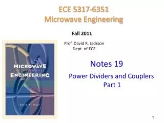
ECE 5317-6351 Microwave Engineering. Fall 2011. Prof. David R. Jackson Dept. of ECE. Notes 19. Power Dividers and Couplers Part 1. Three-port networks. Power Dividers and Directional Couplers. General 3-port:. Power Dividers and Directional Couplers (cont.).

Notes 19
E N D
Presentation Transcript
ECE 5317-6351 Microwave Engineering Fall 2011 Prof. David R. Jackson Dept. of ECE Notes 19 Power Dividers and Couplers Part 1
Three-port networks Power Dividers and Directional Couplers General 3-port:
Power Dividers and Directional Couplers (cont.) For all ports matched, reciprocal, and lossless: Not physically possible (There are three distinct values.) Lossless [S] is unitary These cannot all be satisfied. (If only one is nonzero, we cannot satisfy all three.) At least 2 of S13, S12, S23must be zero. (If only one is zero (or none is zero), we cannot satisfy all three.)
Power Dividers and Directional Couplers (cont.) Now consider a 3-port network that is non-reciprocal, all ports matched, and lossless: “Circulator” These equations will be satisfied if: (There are six distinct values.) 1 2 Lossless or Note that Sij Sji.
Circulators Clockwise (LH) circulator 1 2 Note: We have assumed here that the phases of all the S parameters are zero. Circulators can be made using biased ferrite materials. Counter clockwise (RH) circulator
Power Dividers T-Junction: lossless divider If we match at port 1, we cannot match at the other ports!
Power Dividers (cont.) Assuming port 1 matched: We can design the splitter to control the powers into the two output lines.
Power Dividers (cont.) For each port we have:
Power Dividers (cont.) Also, we have
Power Dividers (cont.) If port 1 is matched: The output ports are not isolated.
Power Dividers (cont.) Powers: Hence
Power Dividers (cont.) Summary • The input port is matched, but not the output ports. • The output ports are not isolated.
Power Dividers (cont.) Example: Microstrip T-junction power divider
Resistive Power Divider Same for Zin1 and Zin2 All ports are matched.
Resistive Power Divider (cont.) By reciprocity and symmetry
Resistive Power Divider (cont.) Hence we have All ports are matched, but 1/2 Pinis dissipated by resistors, and the output ports are not isolated.
Even-Odd Mode Analysis (This is needed for analyzing the Wilkenson.) Obviously, Example: We want to solve for V. using even/odd mode analysis “even” problem “odd” problem
Even-Odd Mode Analysis (cont.) “Even” problem
Even-Odd Mode Analysis (cont.) “Odd” problem short circuit (SC) plane of symmetry
Even-Odd Mode Analysis (cont.) “odd” problem “even” problem By superposition:
Wilkenson Power Divider Equal-split (3 dB) power divider • All ports matched (S11 = S22 = S33 = 0) • Output ports are isolated (S23 = S32 = 0) Note: No power is lost in going from port 1 to ports 2 and 3. Obviously not unitary
Wilkenson Power Divider (cont.) Example: Microstrip Wilkenson power divider
Wilkenson Power Divider (cont.) • Even and odd analysis is required to analyze structure when port 2 is excited. To determine • Only even analysis is needed to analyze structure when port 1 is excited. To determine The other components can be found by using symmetry and reciprocity.
Wilkenson Power Divider (cont.) Top view A microstrip realization is shown. Split structure along plane of symmetry (POS) Even voltage even about POS place OC along POS Odd voltage odd about POS place SC along POS
Wilkenson Power Divider (cont.) How do you split a transmission line? (This is needed for the even case.) top view Voltage is the same for each half of line (V) Current is halved for each half of line (I/2) (magnetic wall) Z0microstrip line For each half
Wilkenson Power Divider (cont.) “Even” Problem Note: The 2Z0 resistor has been split into two Z0 resistors in series. Ports 2 and 3 are excited in phase.
Wilkenson Power Divider (cont.) “Odd” problem Note: The 2Z0 resistor has been split into two Z0 resistors in series. Ports 2 and 3 are excited 180o out of phase.
Wilkenson Power Divider (cont.) Even Problem Port 2 excitation Port 2
Wilkenson Power Divider (cont.) Odd Problem Port 2 excitation Port 2
Wilkenson Power Divider (cont.) We add the results from the even and odd cases together: Note: Since all ports have the same Z0, we ignore the normalizing factor Z0in the S parameter definition. In summary,
Wilkenson Power Divider (cont.) Port 1 excitation Port 1 When port 1 is excited, the response, by symmetry, is even. (Hence, the total fields are the same as the even fields.) Even Problem
Wilkenson Power Divider (cont.) Even Problem Port 1 excitation Hence
Wilkenson Power Divider (cont.) Even Problem Port 1 excitation Along g/4 wave transformer: (reciprocal)
Wilkenson Power Divider (cont.) For the other components: By symmetry: By reciprocity:
Wilkenson Power Divider (cont.) All three ports are matched, and the output ports are isolated.
Wilkenson Power Divider (cont.) • When a wave is incident from port 1, half of the total incident power gets transmitted to each output port(no loss of power). • When a wave is incident from port 2 or port 3, half of the power gets transmitted to port 1 and half gets absorbed by the resistor, but nothing gets through to the other output port.
Wilkenson Power Divider (cont.) Figure 7.15 of PozarPhotograph of a four-way corporate power divider network using three microstrip Wilkinson power dividers. Note the isolation chip resistors.Courtesy of M.D. Abouzahra, MIT Lincoln Laboratory.