Download
1 / 41
410 likes | 537 Views
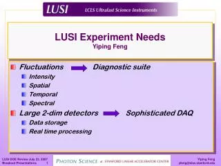
LUSI Experiment Needs Yiping Feng. Fluctuations Diagnostic suite Intensity Spatial Temporal Spectral Large 2-dim detectors Sophisticated DAQ Data storage Real time processing. Electron Beam Characteristics.

E N D
LUSI Experiment NeedsYiping Feng • Fluctuations Diagnostic suite • Intensity • Spatial • Temporal • Spectral • Large 2-dim detectors Sophisticated DAQ • Data storage • Real time processing
Electron Beam Characteristics X-ray Free-Electron Laser (FEL) is fundamentally different from storage-ring based synchrotron sources. For the LCLS • photo-injection at 120 Hz at LCLS • Each macro electron bunch is different at origination • Different timing, length, density • After passing through the Linac including acceleration and compression • Added difference in timing, length, density • Additional difference in energy, orbit • Orbit correction less effective due to low repetition rate in contrast to synchrotron sources (revolution frequency at APS = 272 kHz)
X-ray Beam Characteristics • X-ray amplification process based on self-seeding SASE* • Lasing starts from a random electron density distribution • Each X-ray pulse consists of a random time sequence of spikes of varying degrees of saturation • X-ray FEL exhibits inherent Intensity, spatial, temporal, and spectral fluctuations on pulse by pulse basis *Self Amplification of Spontaneous Emission
Expected Fluctuations of LCLS FEL pulses *To be discussed in details now
Expected Fluctuations of LCLS FEL pulses *To be discussed in details now
Transverse Jitter • Steering coil power supply regulation • Quadrupole magnet transverse vibrations • Quadrupole magnet power supply regulation in presence of typical 200-mm transverse misalignment • RF structure wakefields with varying charge and typical 200-mm transverse misalignments • CSR in bunch compressor chicanes with varying bunch length
Spatial Jitter Transverse Stability Orbit-1a Orbit-1b e- beam X-ray beam Orbit-2a Orbit-2b Pointing Stability
Expected Fluctuations of LCLS FEL pulses *To be discussed in details now
Z-Jitter Dz DR2 DR2 = DZ R1 R2 DR2 = DR1(R2/R1)2
Expected Fluctuations of LCLS FEL pulses *To be discussed in details now
Expected Fluctuations of LCLS FEL pulses *To be discussed in details now
Goals • X-ray diagnostics are required to measure these fluctuations since they can’t be eliminated • Integral parts of Instruments • Timing & intensity measurements for XPP experiments • Wave-front characterization for CXI experiments • Measurements made on pulse-by-pulse basis • Requiring real-time processing by controls/data systems • Commonalities in needs & specs • Standardized and used for all applicable instruments • Modularized for greater flexibility of deployment and placement • Critical diagnostics must be performed and data made available on pulse-by-pulse basis
Fluctuations, 120 hz pulse rate drive DAQ requirements • The 120 Hz per-pulse data collection/reduction, high data rate, large data volume, and sub-ps timing control requirements of LCLS experiments go far beyond those at existing synchrotron sources, requiring considerable complexity and sophistication in controls and data systems’ design, implementation, and integration that are not feasible for individual experimental teams • LCLS/LUSI controls and data systems must • Provide standard controls to all instruments • Support diagnostic measurements • Provide standard data acquisition capabilities • Provide standard data storage and management capabilities • Provide certain standard data analysis capabilities
Data system requirements • Data acquisition • Real-time data processing • Quick view • Data management • On-line storage • Long term archiving/retrieval • Data analysis • Volume rendering • visualization
2D Detectors Plug-play with a common interface?
Data rates - CXI high peak rate & large volume comparable to high-energy physics experiments such as BaBar @ SLAC Is it possible to perform real-time data analysis to reduce the data rate? require high performance and high capacity data acquisition and management system
Per pulse data collection Experimental Diagnostic – EO signal, e- and g beam parameters Raw data rate and volume 2 Gb/sec or higher On-line storage capacity - 20 TB/day Timing/Triggering EO timing measurement < 1 ps Detector trigger < 1 ms Real time analysis Frame correction, quality control To the extent possible - binning, sparsification, FFT Quick view Quasi real-time feedback, 5 frame/s Alignment Data Management Unified data model Archiving capacity – 5 PB/year Analysis staging storage capacity – 20 TB Offline Analysis > 1000 node cluster Overall data needs
Applications needs • User programs • Endstation operation • Calibration • Alignment • Interface to SW for diffraction/scattering experiments • SPEC • Interface to instrumentation/analysis SW • MatLab • LabView • User tools • STRIP tool • ALARM Handler
Pieces of the Puzzle Pulse-by-pulse info exchange High peak rate/ large volume EO Timing & Triggering Feedback Data Archiving/Retrieval Offline Analysis/Rendering
LCLS FEL Parameters *Courtesy of Z. Huang
250 MeV z 0.19 mm 1.6 % 4.30 GeV z 0.022 mm 0.71 % 13.6 GeV z 0.022 mm 0.01 % 6 MeV z 0.83 mm 0.05 % 135 MeV z 0.83 mm 0.10 % Linac-X L =0.6 m rf= -160 Linac-0 L =6 m rf gun L0-a,b Linac-3 L 550 m rf 0° Linac-1 L 9 m rf -25° Linac-2 L 330 m rf -41° 25-1a 30-8c 21-3b 24-6d ...existing linac 21-1 b,c,d undulator L =130 m X BC1 L 6 m R56 -39 mm BC2 L 22 m R56 -25 mm DL1 L 12 m R56 0 DL2 L =275 m R56 0 Commission in Jan. 2008 Commission in Jan. 2007 SLAC linac tunnel research yard LCLS Accelerator Schematics* *Courtesy of P. Emma
Micro-bunching & SASE Process Micro-bunched Shot-noise *Courtesy of Z. Huang
Temporal Characteristic *Courtesy of Z. Huang • DT = 100 - 200 fs • tc ~ 200 as • M = DT/tc ~ 500 -1000 • For ideal e-beam of equal bunch length and same energy • <DI/I> ~ 1/√M ~ 5% • In reality • <DI/I> ~ 1/√M ~ 30% 200-300 attosecond
DE/E DE/E DE/E …or over-compression under-compression sz0 ‘chirp’ z z z sz sE/E V = V0sin(wt) Dz = R56DE/E RF Accelerating Voltage Path Length-Energy Dependent Beamline Magnetic Bunch Compression
250 MeV z 0.19 mm 1.6 % 4.30 GeV z 0.022 mm 0.71 % 13.6 GeV z 0.022 mm 0.01 % 6 MeV z 0.83 mm 0.05 % 135 MeV z 0.83 mm 0.10 % Linac-X L =0.6 m rf= -160 Linac-0 L =6 m rf gun L0-a,b Linac-3 L 550 m rf 0° Linac-1 L 9 m rf -25° Linac-2 L 330 m rf -41° 25-1a 30-8c 21-3b 24-6d ...existing linac 21-1 b,c,d undulator L =130 m X BC1 L 6 m R56 -39 mm BC2 L 22 m R56 -25 mm DL1 L 12 m R56 0 DL2 L =275 m R56 0 Commission in Jan. 2008 Commission in Jan. 2007 SLAC linac tunnel research yard Timing Jitter *Courtesy of P. Emma
Specifications Technically more challenging * Must have high damage threshold
Data Processing • Goals • System Specifications for Data System • Data Acquisition and Management • Data Analysis • XPP, CXI, and XCS Instruments • System Description Gunther Haller’s breakout session
Scope - XPP Instrument time resolved scattering at < ps time resolution
Scope - CXI Instrument structures of single molecules at near atomic resolution Pixelated detector (Cornell detector) Molecule injection Intelligent beam-stop (wave-front sensor) LCLS beam (focused, possibly compressed) Data Processing potential particle orientation beam Readout & reconstruction Optical & x-ray diagnostics To mass spectrometer
Scope - PCS Instrument dynamics of disordered systems at < ns time & near atomic resolutions Data Processing Speckle Pattern (Iron-Aluminum Alloy)
Diagnostics Control - Hartman Wavefront Sensor • Measurement made far from focal plane • Single shot operation • 120 Hz with CCD modification • 1.5 nm and 0.15 nm operation with customization Image obtained from Imagine Optics, Ltd
Timing Control - Temporal Jitter Master Clock Coax RF Distribution Network Accelerating Elements Experimental Pump Laser Electron Gun Sources of Short Term Jitter • Coax RF distribution Network • e-beam phase to RF phase • End Station Laser phase to RF phase Limited to ~ 1 ps !
Timing Control - Electro-optic Sampling Stabilized Fiber Optic RF Distribution (10 fs) LBNL Electro-optic Sampling Laser Pump-probe Laser Gun Laser Sector 20 LTU NEH • Temporal resolution is now limited by: • Our ability to phase lock the lasers to the RF • Intra-bunch SASE jitter
Timing Control - SPPS Laser/X-ray Timing Single shot, Lorentzian fit 100 consecutive shots
Real-time processing – binning in XPP For XPP experiments using 2D detector, Is it possible to perform real-time data analysis to reduce the data rate? • 10 Hz • Point Detector
Real-time Processing – sorting in CXI • Diffraction from a single molecule: noisy diffraction pattern of unknown orientation single LCLS pulse unknown orientation • Combine 105 to 107 measurements into 3D dataset: Reconstruct by Oversampling phase retrieval Classify/sort Average Alignment The highest achievable resolution is limited by the ability to group patterns of similar orientation Real-time? Miao, Hodgson, Sayre, PNAS 98 (2001) Gösta Huldt, Abraham Szöke, Janos Hajdu (J.Struct Biol, 2003 02-ERD-047)
Computing hardware requirements • Real-time computing • Power: 10 Tera-FLOPS • 1000 processor cluster • Memory: 10 -100 GByte RAM • Bandwidth: 100 Gbit/s • Integrated w/ detector or immediate downstream of detector output • Data Storage/Management • 10 – 100 Gbit/s links • 10 – 100 on-line capacity: RAID disks, or flash memory • 10 – 100 staging capacity: RAID disks, or flash memory • 5 Petabyte yearly capacity • ESNET connection for transferring to sister institutes • Offline Analysis • Total FLOPs: 1017 • If analysis done in minutes: 2000 – 40000 processor cluster • Large volume set rendering: 109