Simulation meets formal verification
Simulation meets formal verification. David L. Dill Stanford University. Serdar Tasiran U.C. Berkeley. Why do we care?. Verification is increasingly a bottleneck Large verification teams Huge costs Increases time-to-market Bugs are being shipped

Simulation meets formal verification
E N D
Presentation Transcript
Simulation meets formal verification David L. Dill Stanford University Serdar Tasiran U.C. Berkeley
Why do we care? • Verification is increasingly a bottleneck • Large verification teams • Huge costs • Increases time-to-market • Bugs are being shipped • Simulation and emulation are not keeping up • Formal verification is hard • We need alternatives to fill the gap. David Dill, Serdar Tasiran
Outline • General observations • Conventional answers • Semi-formal methods • Conclusion David Dill, Serdar Tasiran
Orientation • Focus of this talk: Late stage bugs in register transfer level descriptions (and above). • Late stage bugsare hard to find • few bugs per simulation cycle, person-hour • delays time-to-market • Functional errors in RTL are • not eliminated by synthesis • not discovered by equivalence checking. David Dill, Serdar Tasiran
Where do bugs come from? • Incorrect specifications • Misinterpretation of specifications • Misunderstandings between designers • Missed cases • Protocol non-conformance • Resource conflicts • Cycle-level timing errors • … David Dill, Serdar Tasiran
Design scales • Now: • Single FSM: ~12 bits of state, ~30 states • Individual designer subsystem: ~50K gates, 10 FSMs • Major subsystem: ~ 250K gates, 50 FSMs • ASIC: ~2M gates • In a few years: • 10 Billion transistor chips • Lots of reusable IP David Dill, Serdar Tasiran
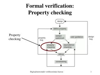
Properties • Verification requires something to check • Properties can be represented in many ways • Temporal logic • Checkers in HDL or other language • Properties can be specified at various points: • End-to-end (black-box) properties. • Internal properties (white-box). [0-In] • Whitebox properties are easier to check, because results don’t have to be propagated to system output. David Dill, Serdar Tasiran
“Coverage” is the key concept • Maximize the probability of • stimulating and detecting bugs, • at minimum cost • (in time, labor, and computation) David Dill, Serdar Tasiran
Outline • General observations • Conventional answers • Semi-formal methods • Conclusion David Dill, Serdar Tasiran
Simulation • Simulation is predominant verification method Gate level or register transfer level (RTL) • Test cases • manually defined, or • randomly generated David Dill, Serdar Tasiran
Functional testing Purgatory Tapeout Typical verification experience Bugs per week Weeks David Dill, Serdar Tasiran
Near-term improvements • Faster simulators • compiled code • cycle simulation • emulation • Testbench authoring tools (Verisity, Vera (Synopsys)) make pseudo-random better/easier • Incremental improvements won’t be enough. David Dill, Serdar Tasiran
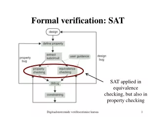
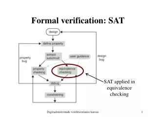
Formal verification • Ensures consistency with specification for all possible inputs (equivalent to 100% coverage of . . . something). • Methods • Equivalence checking • Model checking • Theorem proving • Valuable, but not ageneral solution. David Dill, Serdar Tasiran
Equivalence checking • Compare high level (RTL) with gate level • Gaining acceptance in practice Products: Abstract, Avant!, Cadence, Synopsys, Verplex, … Internal: Veritas (IBM) • But the hard bugs are usually in both descriptions • Targets implementationerrors, not design errors. David Dill, Serdar Tasiran
Model checking • Enumerates all states in state machine. • Gaining acceptance, but not yet widely used. Abstract, Avant!, IBM, Cadence,… Internally supported at Intel, Motorola, ... • Barrier: Low capacity (~200 register bits). • Requires extraction (of FSM controllers) or abstraction (of the design). • Both tend to cause costly false errors. David Dill, Serdar Tasiran
Theorem proving • Theorem prover checks formal proof • Mostly check detailed manual proof. • Sometimes provides some automatic help. • Useful for • verifying algorithms [Russinoff, AMD K7 floating pt] • integrating verification results [Aagard, et al. DAC 98] • Many parts of a big problem can be solved automatically • Theorem prover ensures that parts fit together with no gaps. • Not a general solution (too hard!) David Dill, Serdar Tasiran
Outline • General observations • Conventional answers • Semi-formal methods • Coverage measurement • Test generation • Symbolic simulation • Directed model checking • Conclusion David Dill, Serdar Tasiran
Semi-formal methods • Coverage measurement • Test generation • Symbolic simulation • Model checking for bugs David Dill, Serdar Tasiran
Simulationdriver Simulationengine Monitors Symbolicsimulation ConventionalNovel Diagnosis ofunverifiedportions Vectorgeneration Coverageanalysis How to make simulation smarter • IDEAL:Comprehensive validation without redundant effort • [Keutzer & Devadas] David Dill, Serdar Tasiran
Coverage Analysis: Why? • IDEAL:Comprehensive validation without redundant effort • What aspects of design haven’t been exercised? • Guides vector generation • How comprehensive is the verification so far? • A heuristic stopping criterion • Coordinate and compare • Separate sets of simulation runs • Model checking, symbolic simulation, … • Helps allocate verification resources David Dill, Serdar Tasiran
Coverage Metrics • A metric identifies important • structures in a design representation • HDL lines, FSM states, paths in netlist • classes of behavior • Transactions, event sequences • Metric classification based on level of representation. • Code-based metrics (HDL code) • Circuit structure-based metrics (Netlist) • State-space based metrics (State transition graph) • Functionality-based metrics (User defined tasks) • Spec-based metrics (Formal or executable spec) David Dill, Serdar Tasiran
Simple, cheap Elaborate, expensive Desirable Qualities Of Coverage Metrics • Desirable scenario • IDEAL: Direct correspondence with design errors • 100% coverage = All bugs of a certain type detected 0% 100% Metric 1 Metric 2 . . . Metric n David Dill, Serdar Tasiran
Desirable Qualities Of Coverage Metrics • IDEAL: Direct correspondence with bugs • PROBLEM: No good model for design errors • No analog of “stuck-at faults” for design errors • Bugs are much harder to characterize formally • Difficult to prove that a metric is a good proxy for bugs • Then why use metrics?Need to gauge status of verification. • Heuristic measures of verification adequacy • Coverage guided validation uncovers more bugs • Must look for empirical correlation withbug detection • Higher coverage Þ Higher chance of finding bugs • ~100% coverage ÞFew bugs remain David Dill, Serdar Tasiran
Desirable Qualities Of Coverage Metrics • Direct correspondence with bugs • Ease of use • Tolerable overhead to measure coverage • Reasonable computational and human effort to: • interpret coverage data • achieve high coverage • generate stimuli to exercise uncovered aspects • Minimal modification to validation framework • Every metric is a trade-off between these requirements David Dill, Serdar Tasiran
Coverage Metrics • Code-based metrics • Circuit structure-based metrics • State-space based metrics • Functionality-based metrics • Spec-based metrics David Dill, Serdar Tasiran
Code-Based Coverage Metrics • always @ (a or b or s) // mux • begin • if ( ~s && p ) • d = a; • r = x • else if( s ) • d = b; • else • d = 'bx; • if( sel == 1 ) • q = d; • else if ( sel == 0 ) • q = z • On the HDL description • Line/code block coverage • Branch/conditional coverage • Expression coverage • Path coverage • Tag coverage (more detail later) • Useful guide for writing test cases • Little overhead • A good start but not sufficient • < max. code coverageÞmust test more • Does not address concurrency David Dill, Serdar Tasiran
Code-Based Coverage Metrics • Many commercial tools that can handle large-scale designs • VeriCover (Veritools) • SureCov (SureFire, now Verisity) • Coverscan (DAI, now Cadence) • HDLScore, VeriCov (Summit Design) • HDLCover, VeriSure (TransEDA) • Polaris (formerly CoverIt) (interHDL, now Avant!) • Covermeter (ATC, now Synopsys) • ... David Dill, Serdar Tasiran
Datapath s2 s3 s5 s6 sinit Control s4 Circuit Structure-Based Metrics • Toggle coverage: Is each node in the circuit toggled? • Register activity: Is each register initialized? Loaded? Read? • Counters: Are they reset? Do they reach the max/min value? • Register-to-register interactions:Are all feasible paths exercised? • Datapath-control interface:Are all possible combinations of control and status signals exercised? (0-In checkers have these kinds of measures.) David Dill, Serdar Tasiran
Datapath s2 s3 s5 s6 sinit Control s4 Circuit Structure-Based Metrics • Useful guide for test writers. • Intuitive, easy to interpret. • Not sufficient by themselves. More of a sanity check. • Difficult to determine if • a path is false • a combination of assignments to variables is possible • Problem with all metrics: “Is . . . coverable?” • Ask user or use heuristics David Dill, Serdar Tasiran
Fault detected bya test During test, faulty and original designs behave differently Û Design Fault Coverage • Use faults as proxy for actual design errors. • Faults are local mutations in • HDL code • Gate-level structural description (netlist) • State transition diagram of a finite state machine, … • COVERAGE: Fraction of faults detected by test suite. • Measurement methods similar to fault simulation for mfg. test • [Abadir, Ferguson, Kirkland, TCAD ‘88] • [Kang & Szygenda, ICCD ‘92] • [Fallah, Devadas, Keutzer, DAC ‘98] • . . . David Dill, Serdar Tasiran
Design Fault Coverage: Critique • Various fault models have been considered • Gate (or input) omission/insertion/substitution • Wrong output or wrong next state for given input • Error in assignment on HDL line • Fault models motivated more by ease of use and definition • Not really “common denominators” for design errors • Additional restrictions, e.g. “single fault assumption” • But they provide a fine grain measure of how adequately the design is exercised and observed. David Dill, Serdar Tasiran
Simulationengine Simulationdriver Monitors Symbolicsimulation Diagnosis ofunverifiedportions Coverageanalysis Vectorgeneration Observability • Simulation detects a bug only if • a monitor flags an error, or • design and reference model differ on a variable • Portion of design covered only when • it is exercised(controllability) • a discrepancy originating there causes discrepancy in a monitored variable(observability) • Low observability Þfalse sense of security • Most of the design is exercised • Looks like high coverage • But most bugs not detected by monitors or ref. model • Observability missing from most metrics David Dill, Serdar Tasiran
Tag Coverage [Devadas, Keutzer, Ghosh ‘96] • HDL code coverage metrics+observability requirement. • Bugs modeled as errors in HDL assignments. • A buggy assignment may be stimulated, but still missed • EXAMPLES: • Wrong value generated speculatively, but never used. • Wrong value is computed and stored in memory • Read 1M cycles later, but simulation doesn’t run that long. David Dill, Serdar Tasiran
Tag Coverage [Devadas, Keutzer, Ghosh ‘96] • IDEA: Tag each assignment with +D, -D:Deviation from intended value • 1 + D : symbolic representation of all values > 1 • Run simulation vectors • Tag one variable assignment at a time • Use tag calculus • Tag Coverage: Subset of tags that propagate to observed variables • Confirms that tag is activated and its effect propagated. A+D = 1 A+D = 1 C-D = 4 - k * A+D// k > 0 D? = C-D+ A+D David Dill, Serdar Tasiran
Tag Coverage: Critique • Easily incorporated • can use commercial simulators • simulation overhead is reasonable • Easy to interpret • can identify what blocks propagation of a tag • can use ATPG techniques to cover a tag • Error model doesn’t directly address design errors • BUT a better measure of how well the design is tested than standard code coverage David Dill, Serdar Tasiran
State-Space-Based Metrics (FSM Coverage) • State, transition, or path coverage of “core” FSM:Projection of design onto selected variables • Control event coverage [Ho et al., ‘96, FLASH processor] • Transition coverage for variables controlling datapath • Pair-arcs (introduced by 0-in) • For each pair of controller FSMs, exercise all feasible pairs of transitions. • Catches synchronization errors, resource conflicts, ... • Benjamin, Geist, et. al. [DAC ‘99] • Hand-written abstract model of processor • Shen, Abraham, et.al. • Extract FSM for “most important” control variable • Cover all paths of a given length on this FSM David Dill, Serdar Tasiran
State-Space-Based Metrics • Probably the most appropriate metrics for “bug coverage” • Experience: Rare FSM interactions cause difficult bugs • Addressed best by multiple-FSM coverage • Trade-off: Sophisticated metric on small FSM vs. Simple metric on large FSM/ multiple FSMs. • Relative benefits design dependent. • Difficult to check if something is coverable • May require knowledge of entire design • Most code-coverage companies also provide FSM coverage • Automatic extraction, user-defined FSMs • Reasonable simulation overhead David Dill, Serdar Tasiran
Functional Coverage • Define monitors, tasks, assertions, … • Check for specific conditions, activity, … • User-defined Coverage[Grinwald, et al., DAC ‘98] (IBM) • User defines “coverage tasks” using simple language: • First-order temporal logic + arithmetic operators • Snapshot tasks: Condition on events in one cycle • Temporal tasks: Refers to events over different cycles • User expressions (Covermeter), Vera, Verisity • Assertion synthesis (checkers) (0-in) • Event Sequence Coverage Metrics (ESCMs)[Moundanos & Abraham, VLSI Test Symp. ‘98] David Dill, Serdar Tasiran
Functional Coverage • Good because they make the designer think about the design in a different and redundant way • BUT • May require a lot of user effort (unless synthesized) • User needs to write monitors • May not test corner cases • Designers will write monitors for expected case • Are design specific • Monitors, assertions need to be re-defined for each new design. David Dill, Serdar Tasiran
Spec-Based Metrics • Model-based metrics are weak at detecting missing functionality • The spec encapsulates required functionality • Apply (generalize) design coverage metrics to formal spec • PROBLEMS: • Spec-based metrics alone may not exercise design thoroughly • Spec is often incomplete • Two cases that look equivalent according to specmay be implemented differently • A formal spec may not exist for the unit being tested • Model and spec-based metrics complement each other David Dill, Serdar Tasiran
Semi-formal methods • Coverage measurement • Test generation • Symbolic simulation • Model checking for bugs David Dill, Serdar Tasiran
Verification test generation • Approach: Generate tests automatically that maximize coverage per simulation cycle. • Automatic test generation is crucial for high productivity. • Tests can be generated • off-line: vectors saved in files, or • on-line: vectors generated as you simulate them. • Specific topics • ATPG methods (design fault coverage) • FSM-based methods (FSM coverage) • Test amplification David Dill, Serdar Tasiran
ATPG methods • Use gate-level design fault model • maybe just standard stuck-at model. • Generate tests automatically using ATPG (automatic test pattern generation) techniques • Takes into account “observability” of error. • Oriented towards combinational designs. • General solution would need sequential ATPG [hard]. David Dill, Serdar Tasiran
Design FSM FSM test Design test FSM-based test generation • Generate FSM tests using model checking techniques (e.g. BDD, explicit). • Map FSM test to design test vector [ hard! ] David Dill, Serdar Tasiran
Test vector mapping • User defines mapping rules from FSM event to input vectors. [Ho PhD, Stanford 1996, Geist, et al., FMCAD 96] Mapping must be relatively simple. • Automatically map to test vectors using sequential ATPG techniques. [Moundanos, et al., IEEE TOC Jan. 1998] • Published examples are small. David Dill, Serdar Tasiran
Coverage-driven search • [Ganai, Aziz, Kuehlmann DAC ‘99] • Identify signals that were not toggled in user tests. • Attempts to solve for inputs in current cycle that will make signal toggle using BDDs and ATPG methods. • Similar approach could be taken for other coverage metrics. • General problem: controllability (as in FSM coverage). David Dill, Serdar Tasiran
Test Amplification • Approach: Leverage interesting behavior generated by user. • Explore behavior “near” user tests, to catch near misses. • Many methods could be used • Satisfiability • BDDs • Symbolic simulation + = Formal Simulation 0-In Search David Dill, Serdar Tasiran
Semi-formal methods • Coverage measurement • Test generation • Symbolic simulation • Model checking for bugs David Dill, Serdar Tasiran
Symbolic simulation • Approach: Get a lot of coverage from a few simulations. • Inputs are variables or expressions • Operation may compute an expression instead of a value. • Advantage: more coverage per simulation • one expr can cover a huge set of values. “a” “a + b - c” + “b - c” David Dill, Serdar Tasiran
BDD-based symbolic simulation • Symbolic expressions are represented as BDDs. • Symbolic trajectory evaluation (STE): • Special logic for specifying input/output tests. • Used at MOS transistor or gate level. • COSMOS [Bryant, DAC 90] (freeware), Voss [Seger] • Used at Intel, Motorola • Transistor and RTL simulation • Innologic (commercial) David Dill, Serdar Tasiran