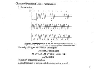
BPSK RF Receiver
BPSK RF Receiver. Team 10 Michael Russell Shawn Kuo Amit Patel. Objective. Successfully demodulate BPSK data sent at RF from one DSP to another Demonstrate feasibility of programmable back-end receiver Develop future tool for DSP lab. End-user Benefits.

BPSK RF Receiver
E N D
Presentation Transcript
BPSK RF Receiver Team 10 Michael Russell Shawn Kuo Amit Patel
Objective • Successfully demodulate BPSK data sent at RF from one DSP to another • Demonstrate feasibility of programmable back-end receiver • Develop future tool for DSP lab
End-user Benefits • A quick and simple point-to-point digital communication solution • Scalable module that is capable of handling multiple demodulation schemes without hardware redesign • Capable of receiving over a large frequency range
Software Implementation • Differential BPSK • Pi-Radian Ambiguity • Symbol Quantization and Unmapping • Phase-Locked Loop • Carrier Recovery • Coherent Detection • Symbol Timing
Simulation Results Generated BPSK Waveform Received BPSK Waveform
Preselector Matching Network Input Impedance
Measured Signals • Transmitted signal • Signal after preselector • Signal after mixing (baseband) • Unfiltered DDS signal (LO) • Filtered DDS signal
Output Interface • Write decoded characters to memory and serial port simultaneously • Interact with serial port through Tera Term
Q I Symbol B Symbol A Q I Symbol B Symbol A Theoretical Probability of Error Constellation Constellation w/Noise
Received Symbol: Q I Symbol B Symbol A Theoretical Probability of Error Mapping Result: Q(sqrt(2*Energy/Noise)) or Q(sqrt(2*SNR))
Calculating SNR The SNR was calculated by measuring separately measuring the signal power and the noise power after the preselector filter.
Calculated Byte Error (upper bound) Took 125KB of data Accurate for large amounts of noise Good order of magnitude approximation for low noise Calculated Probability of Error
Variation in Frequency Drifting in DDS Temperature Result Tolerance of PLL
Successes • Demodulated BPSK data sent at RF from one DSP to another • Demonstrated feasibility of programmable back-end receiver • Breadboard design produced expected behavior
Challenges • Transmitting BPSK signal at RF • Used passive mixer and DDS • Used coaxial channel instead of air • Bandlimiting Signal • Use of Narrow Bandwidth Crystal Filter • Matching Network • Working around Serial Port interrupts
Future Developments Rev1.1 • Solve Serial Port Issues for live data • Printed Circuit Board • Add Faster A/D • Implement more Demodulation Schemes