Download
1 / 24
240 likes | 485 Views
Global Positioning System Receiver and Inter-Satellite Communications RF Design. Soralis Pimentel National Oceanic and Atmospheric Administration (NOAA)-National Environmental Satellite, Data and Information Service (NESDIS), Office of Systems Development

E N D
Global Positioning System Receiver and Inter-Satellite Communications RF Design Soralis Pimentel National Oceanic and Atmospheric Administration (NOAA)-National Environmental Satellite, Data and Information Service (NESDIS), Office of Systems Development National Aeronautics and Space Administration (NASA), Goddard Space Flight Center-Guidance, Navigation and Control Center (GNCC)
GOES Mission • This constellation provide information about meteorological events in the Western atmosphere • GOES-R measurements will result in more accurate weather forecasts, atmosphere, climate, and ocean monitoring.
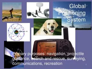
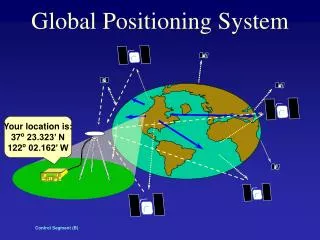
Global Positioning System (GPS) • Satellite radio navigation system • Passive system that uses trilateration positioning method • Array of satellites to measure position, velocity and time • Positioned on the middle earth orbit (MEO) • Designed to measure on the lower earth orbit (LEO) down to earth’s surface • GOES-R GPS application could be used to validate measurements
-130dBm -145dBm
Objectives • To design, build and test Radio Frequency (RF) chains • Magnetospheric Multi Scale (MMS) mission, IRAS: • Down-conversion frequency receiver and power amplification • Up-conversion and phase modulator transmitter • Global Positioning System: • Weak signal down-conversion frequency receiver and power amplification • For future GOES-R applications and others
Design Requirements • GPS receiver: Input of -111dBm at 1.57542 GHz for an output of +4dBm at 35.42MHz • IRAS communications system: • Transmitter: pulse train from a Digital to Analog Converter (DAC) of 2V peak-to-peak of +10dBm input • Receiver: input of -111dBm at 2.05 GHz for an output of +4dBm at 35.42MHz • Power representation
Methodology • Understanding of Electrical Engineering design skills • Study information about RF design • Know the requirements and specifications for the design • Build and test the systems • Data analyses about overall effectiveness of the chain
GPS Receiver LO=1.54GHz -111dBm @1.57542GHz BPF LNA’s LPF -2dBm -2dBm -3dBm +20dBm +20dBm Loss ? -8.5dBm -2dBm Attenuator BPF +3.3dBm @35.42MHz -3dBm Power Amplifier +20dBm Loss ? +24.6dBm +24.6dBm +24.6dBm +24.6dBm
IRAS transmitter LO=2.05GHz BPF LPF +1V -2dBm -2dBm +2.2dBm @2.05GHz -1V Loss ? Center frequency: 2.05GHz B=10MHz -4dBm +20dBm -2dBm Cut-off Frequency: 2MHz +10dBm @1MHz
Low Pass Filter Design • Cut-off frequency= 2MHz @ -1dB, Pass Band Frequency=1.9MHz, Pass Band Ripple= 0.5dB
IRAS Receiver LO=2.01458GHz BPF Center frequency=2.05GHz -111dBm @2.05GHz LPF LNA’s -3dBm +21dBm +21dBm Loss ? -8.5dBm -2dBm BPF Center frequency=35.42MHz Attenuator +4dBm @35.42MHz -3dBm Power Amplifier +20dBm Loss ? +24.6dBm +24.6dBm +24.6dBm +24.6dBm
Acquired Knowledge • Hands-on Engineering design • System requirements and specifications • RF principles and applications • Filter design and implementation • Overall system effectiveness analyses
References • Mistra, Pratap; Enge, Per. Global Positioning System, Signal, Measurements, and Performance Ganga-Jamuna Press, Massachusetts, 2004 • McClaning, Kevin; Vito, Tom. Radio Receiver Design. Noble Publishing Corporation, Atlanta, GA, 2000 • www.minicuircits.com • Jeyasunder, David. Magnetospheric Multi-Scale Mission Observatory/Spacecraft Requirements Document. Code 461 Goddard Space Flight Center, 2005 • Bowick, Chris. RF Circuit Design. Newnes Indianapolis, 1982 • Filter Free design software • NESDIS Office of Systems Development, GOES-R. http://www.osd.noaa.gov/goes_R/
Acknowledgments • NOAA-EPP program, for the opportunity of this internship and the Kennedy Space Center trip • ORISE • Edward Miller, NESDIS-Office of System Development, for mentoring • Greg Boegner, Miriam Wennersten, NASA-Goddard Space Flight Center, GNCC for the opportunity of interrelating a project between NOAA and NASA • NWS Aviation Services Branch
Plans for next summer Find a project that includes both Engineering and Atmospheric Science in order to integrate an interdisciplinary background for Graduate studies consideration.
Inter Satellite Ranging and Alarm System (IRAS) • IRAS is part of MMS • Ranging: • It is used to measure the relative distances among four satellites forming a tetrahedron • Alarm: • Passing packets of orbit data • Pass alarm messages between the observatories
Electrical Engineering Facts • Transmitter: • Source of data informationand process the signal for transmission to another medium • Receiver: • Receives a signal from an external source to process the information • Amplifier: • Integrated circuit that increases the power, voltage or current of a signal • Mixer: • Mixes the RF signal with the local oscillator signal to obtain the IF output.
Electrical Engineering Facts • Filter: sort out unwanted frequency ranges • Low Pass (LPF), High Pass (HPF), Band Pass (BPF), Band Reject (BRF) • Modulation: alter a signal inserting a carrier • Phase Modulation (PM) • Encoding of information into a carrier wave by variation of its phase in accordance with an input signal • Power representation in decibels, dB or dBm
Materials • Amplifiers • Band Pass filters, Low Pass filters • Mixer • Power amplifiers • Attenuators • Coaxial cables • Spectrum analyzer • Power supply and signal generator