Download
1 / 22
220 likes | 369 Views
Final Report of the CLIC-ILC Joint WG on Accelerator General Issues. Ph. Lebrun for the CLIC-ILC Joint WG* CLIC Workshop, CERN 28 January – 1 February 2013. * E. Elsen, M. Harrison, Ph. Lebrun, K. Peach, D. Schulte, K. Yokoya. 2010. 2010.

E N D
Final Report of theCLIC-ILC Joint WG on Accelerator General Issues Ph. Lebrun for the CLIC-ILC Joint WG* CLIC Workshop, CERN 28 January – 1 February 2013 * E. Elsen, M. Harrison, Ph. Lebrun, K. Peach, D. Schulte, K. Yokoya
Joint WG on « Accelerator General Issues » • Membership: • CLIC: Ph. Lebrun (co-chair), K. Peach, D. Schulte • ILC: E. Elsen, M. Harrison (co-chair), K. Yokoya • Mandate • The ILCSC and the CLIC Collaboration Board have approved formation of a CLIC/ILC General Issues working group with the following mandate: • Promoting the Linear Collider • Identifying synergies to enable the design concepts of ILC and CLIC to be prepared efficiently • Discussing detailed plans for the ILC and CLIC efforts, in order to identify common issues regarding siting, technical items and project planning. • Discussing issues that will be part of each project implementation plan • Identifying points of comparison between the two approaches to the linear collider • Reporting line • The conclusions of the working group will be reported to the ILCSC and CLIC Collaboration Board with a goal of producing a joint document
37 meetings of the WG 10 November 2009 Webex 7 December 2009 Webex 5 January 2010 Face-to-face Oxford 8 March 2010 Webex 28 March 2010 Face-to-face Beijing 10 May 2010 Webex 24 July 2010 Face-to-face Paris 12 August 2010 Webex 27 September 2010 Webex 15 October 2010 Face-to-face CERN 29 November 2010 Webex 20 January 2011 Webex 21 February 2011 Webex 14 March 2011 Face-to-face CERN 11 April 2011 Webex 3 May 2011 Face-to-face CERN 17 June 2011 Webex 14 July 2011 Webex 28 July 2011 Face-to-face CERN 12 September 2011 Face-to-face CERN 28 September 2011 Face-to-face Granada 24 October 2011 Webex 21 November 2011 Webex 5 December 2011 Webex 19 December 2011 Webex 1 February 2012 Face-to-face Oxford 12 March 2012 Face-to-face CERN 8 May 2012 Face-to-face CERN 29 August 2012 Webex 3 October 2012 Webex 9 October 2012 Webex 25 October 2012 Face-to-face Arlington 3 December 2012 Webex 21 December 2012 Webex 11 January 2013 Webex 25 January 2013 Webex 30 January 2013 Fuze Meeting
First Interim Report – January 2011 • “Identifying synergies to enable the design concepts of ILC and CLIC to be prepared efficiently” • Survey of CLIC-ILC collaboration throughtopical joint working groups • Possible re-use of ILC infrastructure for CLIC • “Discussing detailed plans for the ILC and CLIC efforts, in order to identify common issues regarding siting, technical items and project planning” • Comparative projectroadmaps and milestones • Statement on siting • R&D programs and technicalmilestones • Project planning
Second Interim Report – January 2012 • “Identifying synergies to enable the design concepts of ILC and CLIC to be prepared efficiently” • Assessment and future of the topical joint working groups • “Discussing issues that will be part of each project implementation plan” • More on siting • Power and energyconsiderations • Industrialprocurement for large acceleratorsystems • Decisionprocess
Final Report – January 2013 • Address remaining point of the mandate“Identify points of comparison between the two approaches to the Linear Collider” • Cruciallyenabled by completion in 2012 of • CLIC CDR and Value Estimate (reviewed in 2012) • ILC TDR and Value Estimate(underreview) • Accelerator technology • Design maturityconcerningenergyreach • Design maturityconcerningluminosityreach • System tests • Costestimate • Methodology & assumptions • Value estimatesat 500 GeV • Costscalingwith collision energy • Power & energyconsiderations • Power estimatesat 500 GeV • Power scalingwith collision energy and luminosity • Standby modes & energy management • Pathstowardsenergyefficiency
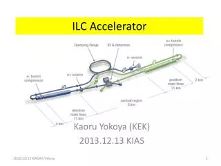
Layout of ILC at 500 GeV Polarised electron source Damping Rings Ring to Main Linac (RTML) (inc. bunch compressors) e+ Main Linac Beam Delivery System (BDS) & physics detectors Beam dump Polarised positronsource e- Main Linac
Accelerator technologyEnergyreach [1/2] • Accelerating gradient • ILC goal ≥ 31.5 MV/m on averageat Q0 ≥ E+10, equivalent to 35 MV/m achieved on vertical tests stand, validated on 16 cavities • European X-FEL production willestablishstatisticalsignificance • ILC cavitytechnologycanbeconsidered mature • Two CLIC structures have exceeded 100 MV/m (withoutbeamloading) withlow breakdown rate compatible withlinacoperation • Beamloading tests at CTF3 in 2013 • Next major goal is to optimize the CLIC structure design and producesmallseries prototypes • RF power components • Main RF sources for bothprojects are pulsed L-band klystrons, 1.3 GHz & 10 MW for ILC, 1 GHz and 15 MW for CLIC drive beam • ILC pulse lengthorder of magnitude longer, repetition rate 10 times smaller, hencesimilaraverage power and lower pulse energy for CLIC • ILC klystrons commerciallyavailable, new technologytestedsuccessfullyfor modulators • Prototype development for CLIC klystrons and modulators to bedone
Accelerator technologyEnergyreach [2/2] • RF unit system test • ILC RF unit operatedwithbeamwithparameters close to ILC design • CLIC drive beam concept demonstratedat CTF3, total current about 1/3 of needed for CLIC. Detailed simulations of beamstability and quality, usingrealisticwakefields and imperfections, show that design targets for drive beamaccelerator, combiner rings and deceleratorscanbereached • Prototype two-beam modules for main linacunder construction • Development prototypes of 1 GHz klystrons and modulatorscanbeused for building full-current drive-beamfacility, required for power tests of series CLIC modules
Accelerator technologyLuminosityreach [1/3] • Sources • Both ILC and CLIC use a polarizedelectron source (yielding 80 % polarizationat IP) • ILC positron source uses helicalundulator on electronbeam, (polarization ~30 %, couldbepotentiallyincreased to 60 % with photon collimation) • CLIC uses conventional positron source (no polarization), other options considered for polarized positrons which do not use the electronbeam • Veryappropriatedomain for continued CLIC-ILC collaboration • Damping rings • Challenging for bothprojects, but relying on vastexperiencewith modern light sources and test facilities (ATF2 at KEK, CESR-TA atCornell) • More demanding CLIC wiggler: prototype to betestedwithbeamsoon • Collective instabilities (e.g. electroncloud) studied by simulation and experiment, mitigation techniques tested • Need for stable extraction: prototype kicker for ILC successfullytestedat ATF2, for CLIC under construction • Continued CLIC-ILC collaboration, alsobenefittingothercommunities
Accelerator technologyLuminosityreach [2/3] • Main linacs • Damping of long-range wakefields essential, in ILC extracted by antennas, in CLIC by waveguidesintegratedintoaccelerating structures • Short-range wakefields more important in CLIC, need BNS damping • Small vertical emittances for bothprojects, need to bepreserved first by mechanicalprealignment. ILC achieves ~300 mm in cryomodule, CLIC needs 10 mm (13 mm achieved) • Thenbeam-basedalignment for bothprojects, by dispersion-free steering. CLIC uses wake-field monitors to measurebeam offset wrt structures • Bothprojectsexpected to preservebeamqualityalong main linacsnecessary to achieveluminosity goals • Beamdelivery system • Final focus systems of CLIC and ILC based on sameprinciple • Finitecrossing angle necessary to removespentbeams, 14 mradianat ILC, 18.6 mradianat CLIC 500 • Critical components are final quadrupoles, CLIC has short prototype • Most important beamdynamics issue istuning of complexoptics to reachsmall spot size at IP: more R&D needed, collaboration useful
Accelerator technologyLuminosityreach [3/3] • Machine stability • Both CLIC & ILC are seneitive to dynamic imperfections, ground motion & technical noise: ILC more tolerant as one can use intra-pulse feedback • Ground motion strongly site-dependent • CLIC has developed passive and active stabilizationsystems: performance of active system testedsuccessfully on prototypes • Machine protection • Veryenergetic and brilliantbeamsat end of linacs have domagepotential for both machines • Combination of passive and active protection measures • More detailedworkrequired
CostsMethodology • CLIC and ILC use «value estimate» + «explicit labor» methodology • Project baseline • ILC costsderivedfrom 500 GeVbaseline machine, as described in TDR • CLIC costsat 500 GeV and 1.4/1.5 TeVderivedfromintermediate stages of 3 TeVbaseline as described in CDR • Two scenarios for CLIC at 500 GeV: A (luminosityoptimized) & B (lower entry cost) • No attempt to investigate first stages atlowerenergy («Higgsfactory»), including klystron-powered CLIC underconsideration • Currencies, conversion & escalation • ILC costsexpressed in ILCU (= USD of 2012), convertedusing PPP (OECD) • CLIC costsexpressed in CHF of Dec 2010, convertedusing exchange rates and escalatedusingSwiss indices • Labor • ILC uses bottom-up approach, CLIC scalesgloballyfrom LHC data • Bothapproachesyieldsimilarresultsat ~ 24 million person.hours • Reviewing • ILC TDR costsunderreview (Feb 2012), hence no precisenumbersquotedhere • CLIC CDR costsreviewedFeb 2011 • Coststakenat face value, i.e. no attempt to validatethem • Precision of value estimates ~ 25 %
Value estimatesat 500 GeV Conventionalfacilities are a major costelement
Value vs center-of-mass energy of CLIC and ILC Incrementalcost for CLIC ~ 4 MCHF/GeVmuchlowerthan for ILC Position of cross-over point sensitive to value uncertainty
Power & energy • Linearcolliders are single-pass machines, hence power-hungry • Power efficiency • «intrinsic» efficiency, i.e. luminosity per beam power, maximized by lowemittance and strong FF • «technological» efficiency, i.e. electricalgridto beam, maximized by developments in RF and otheracceleratorsystems • Power stronglydependent on beamenergy and luminosity • Power consumption, and not only construction cost, willeventuallylimit the practicalenergy range of linearcolliders • Single largest fraction of electrical power used for main linac RF systems • Still, only ~1/3 of total for CLIC and ILC • Injectorcomplex and conventionalfacilities are bigusers, withstrongdifferencesbetween CLIC and ILC • From power to energy • CLIC shows significantlyreduced power in standby modes • Possibility of modulatingoperation off periods of peak power demand • Reducing power consumptionis essential for bothprojects, e.g. through • High-efficiency RF power sources • Reduction of ohmiclosses in electromagnets and cables • Wasteheatrecovery and valorization
Nominal power at 500 GeV Substantialdifferences on conventionalfacilities
Power vs center-of-mass energy of CLIC and ILC 3.7 E34 cm-2.s-1 5 E34 cm-2.s-1 2.3 E34 cm-2.s-1 1.3 E34 cm-2.s-1 1.8 E34 cm-2.s-1