Enhancements in Upper Wave Detection Using MSG Satellite Imagery
This report discusses the comparative analysis of Meteosat Transition Programme (MTP) channels with corresponding MSG (Meteosat Second Generation) channels in detecting upper wave phenomena. We explore the use of infrared (IR) images alongside relevant numerical weather prediction (NWP) parameters, as well as different channel combinations. The enhanced spatial resolution of MSG imagery, including better delineation of contours and cloud structures, provides significant improvements in identifying water and ice clouds. This evaluation spotlights the shifts in cloud systems between MTP and MSG images and their implications for meteorological forecasting.

Enhancements in Upper Wave Detection Using MSG Satellite Imagery
E N D
Presentation Transcript
Conceptual Models (CMs):Wave - Upper wave How to use MSG satellite images similarities to and improvements over MTP Contact person: Veronika Zwatz-Meise zwatz-meise@zamg.ac.at Version 1.0. 13 July 2004
CM:Wave - Upper wave • MTP channels in comparison with the corresponding MSG channels • CM Wave: IR image + relevant NWP parameters • MSG additional channels + Channel combinations • WV and WV difference images
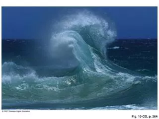
MTP: ir As the image time between MTP and MSG differs, a shift between the cloud systems can be noticed in the two images
MSG: ch09 Sharper contours through improved space resolution
MSG: ch01 Looks relatively similar; but: somewhat coarser space resolution
MSG:129 Sharper contours and more detailed grey-shades through improved space resolution in IRand additional information from 2 different VIS channels
CM:Wave - Upper wave • MTP channels in comparison with the corresponding MSG channels • CM Wave: IR image + relevant NWP parameters • MSG additional channels + Channel combinations • WV and WV difference images
H1000 Upper wave: No or only very weak surface minimum
H500 Wave and upper wave: Upper level trough at rear side of front
Equ. Thickness + TFP Thickness gradient and TFP; transition from Kata to Anatype; TFP at leading edge typical for upper wave
TFP + TA 700 hPa Upper wave: CA at 700 hPawithin whole cloud band
H500 + PVA Upper level trough at rear side of front PVA max along as well as above frontal cloud band
CM:Wave - Upper wave • MTP channels in comparison with the corresponding MSG channels • CM Wave: IR image + relevant NWP parameters • MSG additional channels + Channel combinations • WV and WV difference images
Recognition of water and ice clouds: dark grey: ice clouds white: water clouds CH03
134 4 different colours within upper wave: different cloud layers and stages
149 4 different colours within upper wave: different cloud layers and stages
139 4 different colours within upper wave: different cloud layers and stages; best separation between colours
CM:Wave - Upper wave • MTP channels in comparison with the corresponding MSG channels • CM Wave: IR image + relevant NWP parameters • MSG additional channels + Channel combinations • WV and WV difference images
Ch05 Distinct black stripe only in upper layers grey area in both levels; darker in the lower layer No big difference between the two channels: cloud edge
Example for dry air in lower levels below frontal surface and jet axis wet dry wet dry