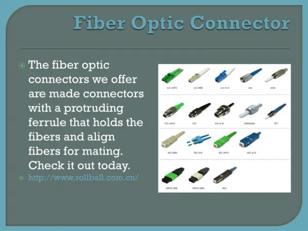
Introduction to Programmable Logic Controllers (PLCs): Basics & Applications
This training provides a comprehensive introduction to the hardware and software components of Programmable Logic Controllers (PLCs). Participants will learn about the architecture, instruction sets, programming techniques, and the operational features of PLCs. The course emphasizes the advantages of PLCs over traditional relay systems and covers troubleshooting, maintenance, and practical applications. By the end of the training, participants will be equipped to describe PLC components, interpret specifications, apply troubleshooting techniques, and program PLCs for various applications.


Introduction to Programmable Logic Controllers (PLCs): Basics & Applications
E N D
Presentation Transcript
Description This training introduces the basic hardware and software components of a Programmable Controller (PLC). It details the architecture and basic instruction set common to all PLC’s. Basic programming techniques and logic designs are covered. This training describes the operating features of the PLC, the advantages of the PLC over hard-wired control systems, practical applications, troubleshooting and maintenance of PLC’s. 2
Objectives At the end of the training the participants should be able to: • Describe the major components of a common PLC. • Interpret PLC specifications. • Apply troubleshooting techniques. • Convert conventional relay logic to a PLC language. • Operate and program a PLC for a given application. 3
Course Contents • History of Programmable Controllers • Relay Ladder Logic • Central Processing Unit • Input/Output System • Programming and Peripheral Devices • Programming Concepts • Applications • Troubleshooting and Maintenance 4
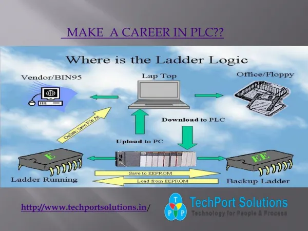
INTRODUCTION TO PLCS Advantages of PLCs • Less wiring. • Wiring between devices and relay contacts are done in the PLC program. • Easier and faster to make changes. • Trouble shooting aids make programming easier and reduce downtime. • Reliable components make these likely to operate for years before failure.
PLC Origin • - Developed to replace relays in the late 1960s • - Costs dropped and became popular by 1980s • - Now used in many industrial designs
Historical Background The Hydramatic Division of the General Motors Corporation specified the design criteria for the first programmable controller in 1968 Their primary goal To eliminate the high costs associated with inflexible, relay-controlled systems. 7
Historical Background • The controller had to be designed in modular form, so that sub-assemblies could be removed easily for replacement or repair. • The control system needed the capability to pass data collection to a central system. • The system had to be reusable. • The method used to program the controller had to be simple, so that it could be easily understood by plant personnel. 8
Programmable Controller Development 1968 Programmable concept developed 1969 Hardware CPU controller, with logic instructions, 1 K of memory and 128 I/O points 1974 Use of several (multi) processors within a PLC - timers and counters; arithmetic operations; 12 K of memory and 1024 I/O points 1976 Remote input/output systems introduced 1977 Microprocessors - based PLC introduced 9
Programmable Controller Development 1980 Intelligent I/O modules developed Enhanced communications facilities Enhanced software features (e.g. documentation) Use of personal microcomputers as programming aids 1983 Low - cost small PLC’s introduced 1985 on Networking of all levels of PLC, computer and machine using SCADA software. 10
Programmable Logic Controllers ( Definition according to NEMA standard ICS3-1978) A digitally operating electronic apparatus which uses a programming memory for the internal storage of instructions for implementing specific functions such as logic, sequencing, timing, counting and arithmetic to control through digital or analog modules, various types of machines or process. 11
Leading Brands Of PLC AMERICAN 1. Allen Bradley 2. Gould Modicon 3. Texas Instruments 4. General Electric 5. Westinghouse 6. Cutter Hammer 7. Square D EUROPEAN 1. Siemens 2. Klockner & Mouller 3. Festo 4. Telemechanique 12
Leading Brands Of PLC JAPANESE 1. Toshiba 2. Omron 3. Fanuc 4. Mitsubishi 13
Areas of Application • Manufacturing / Machining • Food / Beverage • Metals • Power • Mining • Petrochemical / Chemical 14
PLC Size 1. SMALL - it covers units with up to 128 I/O’s and memories up to 2 Kbytes. - these PLC’s are capable of providing simple to advance levels or machine controls. 2. MEDIUM - have up to 2048 I/O’s and memories up to 32 Kbytes. 3. LARGE - the most sophisticated units of the PLC family. They have up to 8192 I/O’s and memories up to 750 Kbytes. - can control individual production processes or entire plant. 15
MOTOR A FS B C TIMER Tank Used to Mix Two Liquids FLOAT SWITCH SOLENOIDS SOLENOID 1 -MINUTE 16
Tank Used to Mix Two Liquids A tank is used to mix two liquids. The control circuit operates as follows: 1. When the start button is pressed, solenoids A and B energize. This permits the two liquids to begin filling the tank. 2. When the tank is filled, the float switch trips. This de-energizes solenoids A and B and starts the motor used to mix the liquids together. 3. The motor is permitted to run for one minute. After one minute has elapsed, the motor turns off and solenoid C energizes to drain the tank. 17
Tank Used to Mix Two Liquids 4. When the tank is empty, the float switch de-energizes solenoid C. 5. A stop button can be used to stop the process at any point. 6. If the motor becomes overloaded, the action of the entire circuit will stop. 7. Once the circuit has been energized it will continue to operate until it is manually stopped. 18
POWER SUPPLY I M N O P D U U T L E O M U O T D P U U L T E PROCESSOR From SENSORS To OUTPUT Pushbuttons, contacts, limit switches, etc. Solenoids, contactors, alarms etc. PROGRAMMING DEVICE Major Components of a Common PLC 19
Major Components of a Common PLC POWER SUPPLY Provides the voltage needed to run the primary PLC components I/O MODULES Provides signal conversion and isolation between the internal logic- level signals inside the PLC and the field’s high level signal. 20
Major Components of a Common PLC PROCESSOR Provides intelligence to command and govern the activities of the entire PLC systems. PROGRAMMING DEVICE used to enter the desired program that will determine the sequence of operation and control of process equipment or driven machine. 21
Programming Device • Also known as: • Industrial Terminal ( Allen Bradley ) • Program Development Terminal ( General Electric ) • Programming Panel ( Gould Modicon ) • Programmer ( Square D ) • Program Loader ( Idec-Izumi ) • Programming Console ( Keyence / Omron ) 22
Programming Device • Types: • Hand held unit with LED / LCD display • Desktop type with a CRT display • Compatible computer terminal 23
I/O Module • The I/O interface section of a PLC connects it to external field devices. • The main purpose of the I/O interface is to condition the various signals received from or sent to the external input and output devices. • Input modules converts signals from discrete or analog input devices to logic levels acceptable to PLC’s processor. • Output modules converts signal from the processor to levels capable of driving the connected discrete or analog output devices. 24
IS NEEDED TO: • Prevent voltage transients from damaging the processor. • Helps reduce the effects of electrical noise USE TO DROP THE VOLTAGE TO LOGIC LEVEL Buffer, Filter, hysteresis Circuits Current Limiting Resistor FROM INPUT DEVICE OPTO- ISOLATOR TO PROCESSOR I/O Module DC INPUT MODULE 25
IS NEEDED TO: • Prevent voltage transients from damaging the processor. • Helps reduce the effects of electrical noise CONVERTS THE AC INPUT TO DC AND DROPS THE VOLTAGE TO LOGIC LEVEL Buffer, Filter, Hysteresis Circuits Rectifier, Resistor Network FROM INPUT DEVICE OPTO- ISOLATOR TO PROCESSOR I/O Module AC INPUT MODULE 26
IS NEEDED TO: • Prevent voltage transients from damaging the processor. • Helps reduce the effects of electrical noise Amplifier RELAY TRIAC X’SISTOR TTL Circuits OPTO- ISOLATOR I/O Module DC / AC OUTPUT MODULE FROM PROCESSOR TO OUTPUT DEVICE 30
I/O Circuits DIFFERENT TYPES OF I/O CIRCUITS 1. Pilot Duty Outputs Outputs of this type typically are used to drive high-current electromagnetic loads such as solenoids, relays, valves, and motor starters. These loads are highly inductive and exhibit a large inrush current. Pilot duty outputs should be capable of withstanding an inrush current of 10 times the rated load for a short period of time without failure. 32
I/O Circuits 2. General - Purpose Outputs These are usually low- voltage and low-current and are used to drive indicating lights and other non-inductive loads. Noise suppression may or may not be included on this types of modules. 3. Discrete Inputs Circuits of this type are used to sense the status of limit switches, push buttons, and other discrete sensors. Noise suppression is of great importance in preventing false indication of inputs turning on or off because of noise. 33
I/O Circuits 4. Analog I/O Circuits of this type sense or drive analog signals. Analog inputs come from devices, such as thermocouples, strain gages, or pressure sensors, that provide a signal voltage or current that is derived from the process variable. Standard Analog Input signals: 4-20mA; 0-10V Analog outputs can be used to drive devices such as voltmeters, X-Y recorders, servomotor drives, and valves through the use of transducers. Standard Analog Output signals: 4-20mA; 0-5V; 0-10V 34
I/O Circuits 5. Special - Purpose I/O Circuits of this type are used to interface PLCs to very specific types of circuits such as servomotors, stepping motors PID (proportional plus integral plus derivative) loops, high-speed pulse counting, resolver and decoder inputs, multiplexed displays, and keyboards. This module allows for limited access to timer and counter presets and other PLC variables without requiring a program loader. 35
OUTPUTS INPUTS MOTOR CONTACTOR LAMP PUSHBUTTONS PLC
L2 L1 Allen-Bradley 1746-1A16 I= Input Module slot # in rack I:2 0 Module Terminal # P. B SWITCH Address I:2.0/0 LADDER PROGRAM INPUT MODULE WIRING DIAGRAM
CONTACTOR L2 L1 N.O MOTOR L2 • SOLENOID • VALVES • LAMP • BUZZER C L1 FIELD WIRING OUTPUT MODULE WIRING O:4 L1 L2 0 CONTACTOR LADDER PROGRAM
Discrete Input A discrete input also referred as digital input is an input that is either ON or OFF are connected to the PLC digital input. In the ON condition it is referred to as logic 1 or a logic high and in the OFF condition maybe referred to as logic o or logic low. Normally Open Pushbutton Normally Closed Pushbutton Normally Open switch Normally Closed switch Normally Open contact Normally closed contact
IN OFF Logic 0 PLC Input Module 24 V dc IN OFF Logic 1 PLC Input Module 24 V dc
Analog Input An analog input is an input signal that has a continuous signal. Typical inputs may vary from 0 to 20mA, 4 to 20mA or 0 to10V. Below, a level transmitter monitors the level of liquid in the tank. Depending on the level Tx, the signal to the PLC can either increase or decrease as the level increases or decreases. IN PLC Analog Input Module Level Transmitter Tank
Digital Output A discrete output is either in an ON or OFF condition. Solenoids, contactors coils, lamps are example of devices connected to the Discrete or digital outputs. Below, the lamp can be turned ON or OFF by the PLC output it is connected to. OUT PLC Digital Output Module Lamp
Analog Output An analog output is an output signal that has a continuous signal. Typical outputs may vary from 0 to 20mA, 4 to 20mA or 0 to10V. Electric to pneumatic transducer OUT E Supply air P PLC Analog Output Module 0 to 10V Pneumatic control valve
Processor The processor module contains the PLC’s microprocessor, its supporting circuitry, and its memory system. The main function of the microprocessor is to analyze data coming from field sensors through input modules, make decisions based on the user’s defined control program and return signal back through output modules to the field devices. Field sensors: switches, flow, level, pressure, temp. transmitters, etc. Field output devices: motors, valves, solenoids, lamps, or audible devices. The memory system in the processor module has two parts: a system memory and an application memory. 44
SYSTEM APPLICATION Memory Map Organization • System memory includes an area called the EXECUTIVE, composed of permanently-stored programs that direct all system activities, such as execution of the users control program, communication with peripheral devices, and other system activities. • The system memory also contains the routines that implement the PLC’s instruction set, which is composed of specific control functions such as logic, sequencing, timing, counting, and arithmetic. • System memory is generally built from read-only memory devices. • The application memory is divided into the data table area and user program area. • The data table stores any data associated with the user’s control program, such as system input and output status data, and any stored constants, variables, or preset values. The data table is where data is monitored, manipulated, and changed for control purposes. • The user program area is where the programmed instructions entered by the user are stored as an application control program. • Data Table • User Program 45
Memory Designs VOLATILE. A volatile memory is one that loses its stored information when power is removed. Even momentary losses of power will erase any information stored or programmed on a volatile memory chip. Common Type of Volatile Memory RAM.Random Access Memory(Read/Write) Read/write indicates that the information stored in the memory can be retrieved or read, while write indicates that the user can program or write information into the memory. 46
Memory Designs The words random access refer to the ability of any location (address) in the memory to be accessed or used. Ram memory is used for both the user memory (ladder diagrams) and storage memory in many PLC’s. RAM memory must have battery backup to retain or protect the stored program. 47
Memory Designs Several Types of RAM Memory: 1.MOS 2.HMOS 3.CMOS The CMOS-RAM (Complimentary Metal Oxide Semiconductor) is probably one of the most popular. CMOS-RAM is popular because it has a very low current drain when not being accessed (15microamps.), and the information stored in memory can be retained by as little as 2Vdc. 48
Memory Designs NON-VOLATILE Has the ability to retain stored information when power is removed, accidentally or intentionally. These memories do not require battery back-up. Common Type of Non-Volatile Memory ROM, Read Only Memory Read only indicates that the information stored in memory can be read only and cannot be changed. Information in ROM is placed there by the manufacturer for the internal use and operation of the PLC. 49
Memory Designs Other Types of Non-Volatile Memory PROM,Programmable Read Only Memory Allows initial and/or additional information to be written into the chip. PROM may be written into only once after being received from the PLC manufacturer; programming is accomplish by pulses of current. The current melts the fusible links in the device, preventing it from being reprogrammed. This type of memory is used to prevent unauthorized program changes. 50