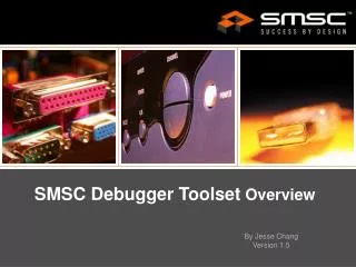
SMSC Debugger Toolset Overview
SMSC Debugger Toolset Overview. By Jesse Chang Version 1.5. Introduction. The Pegasus debugger Toolset provides a full set of integrated tools helpful to PC keyboard controller hardware and firmware development during the design phase.

SMSC Debugger Toolset Overview
E N D
Presentation Transcript
SMSC Debugger Toolset Overview By Jesse Chang Version 1.5
Introduction • The Pegasus debugger Toolset provides a full set of integrated tools helpful to PC keyboard controller hardware and firmware development during the design phase. • A fully configured design will support a USB2.0 based high speed serial flash programmer, a USB2.0 based trace debugger, a UART based ROM monitor, and a UART based serial flash programmer.
Pegasus Mechanical Description PEGASUS PCB OVERVIEW
System Development SMSC KBC/EC 1100 Environment (Pegasus Toolkit)
USB-TO-TARGET CONNECTOR CONFIGURATION • The SMSC Debug Trace environment was designed for the purpose of easing BIOS development, firmware development, and system debug. The trace method developed by SMSC is non-intrusive, minimizing the debugging tool’s impact on actual code implementation. Data is written to either the FLASH Memory bus or the SMSC Serial Debug Port (for targets that have one) in a very low overhead format. The extra XDATA space writes (0x7FBA) make only marginal differences in code execution speed. Furthermore, this method allows debug data to be gathered without activation of any normally unused chip hardware, such as the serial port, making it more closely emulate the actual firmware implementation. • Firmware coding for Pegasus board initialization rMultiplx_12_95_88 = 0x08;// MMCR 0x7f65 rMultiplx_12_95_88 == 0x08 for TFIFO INIT. rGPIO_N_DIR_45_38 |= 0x02; // Set 0x7FCC bit 1, which sets GPIO39's direction as output. // the default output is low (0). rGPIO_N_OUT_45_38 |= 0x02;// Set 0x7FCD bit 1, which sets GPIO39 output as Hi to release // Pegasus's reset signal.
SMSC Debug Trace acquisizer • Either Windows 2000 or Windows XP operation system is required. • There is no installation program. Just copy USB_DFT.exe to a working directory and execute it after trace FIFO board is connected.
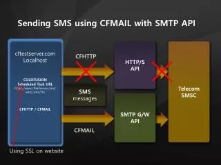
UART CONFIGURATION • Serial FLASH Programmer The SMSC Serial Flash Programming Interface is used as a remedial measure for Flash crisis recovery. When the VCC1 supply is asserted, the SFPI_EN strap option can enable the Serial Flash Programming Interface. An external 1.8432MHz clock must be provided using the 1.8432MHZ_IN pin, which is an alternate function of the LGPIO77 pin. When the Serial Flash Programming Interface is enabled, the 8051 executes bootstrap code from a small internal ROM that allows the 8051 to send and receive data using the 8051-Driven 16550 UART to download firmware to the 8051 Scratch Memory. This firmware can be used to reprogram the Flash. This feature of this configuration is intended for use with the SMSC Serial FLASH Programming Utility.
Serial FLASH Programming Utility • Using the Serial Flash Programming Interface an SMSC KBC device’s 8051 can execute bootstrap code from a small internal ROM. That code allows the 8051 to send and receive data using its 16550 UART to download firmware to Scratch Memory. • Also provides a compact set of debug capabilities.
Serial FLASH Programming Utility Installation • Boot the Host PC to Windows 2000 or Windows XP. • Execute the SFPU installation program setup.exe. • Follow the on screen instructions.
GUI of Serial FLASH Programming Utility (Debugger : Read From Scratch ROM)
GUI of Serial FLASH Programming Utility (Debugger : Write Internal Memory)
Connection to Pegasus companion KBC/EC 1100 EVB Via UARTDirectly Without Pegasus ROM EMULATOR CONNECTION RS232 NULL MODEM (Pin 2 (Tx) and Pin 3 (Rv) are connected crosswise)
KBC1100 EVB UNIROM HEADER PIN-OUTS FOR ROM EMULATOR A ROM emulator usually connects to the target board using a ribbon cable. One end of the ribbon cable has a DIP connector that plugs into a FLASH memory socket and the other end has an IDS connector that plugs into the ROM emulator. If your ROM emulator connector has one of the following IDS pin-outs, then it can be used with the KBC1100 EVB. Note: The EconoROMIII and UniROM from TechTools have a IDS pin-out A connector
Terminal Display of KBC/EC 1100 Demo program (UART connecting directly)