Download
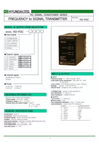
1 / 18
180 likes | 297 Views
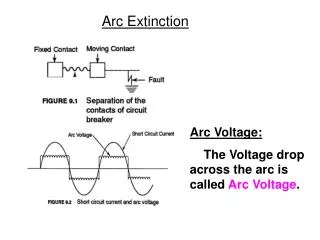
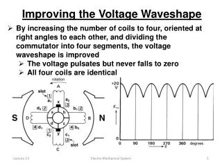
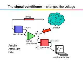
The signal conditioner -- changes the voltage. Amplify Attenuate Filter. Electrical Drawings. Symbols Wires are straight lines usually horizontal and vertical Connection points are shown as circles on the end of a wire:

E N D
The signal conditioner -- changes the voltage Amplify Attenuate Filter
Electrical Drawings • Symbols • Wires are straight lines usually horizontal and vertical • Connection points are shown as circles on the end of a wire: • Ground is a common connection point from which most voltages are measured: • Shown as either a small triangle: • or as a set of lines forming a triangle: • Resistors are shown as zigzag lines, vertical or horizontal:
V+ + Vn _ + Vo - +Vp - V- Operational Amplifiers -- a.k.a. “op-amps” • Practical signal amplifiers are frequently constructed from inexpensive, integrated circuit “chips” called operational amplifiers. • The circuit symbol for an op-amp is a triangle (see Figure 3.10a).
V+ + Vn _ + Vo - +Vp - V- Operational Amplifiers -- a.k.a. “op-amps” • A circuit containing an op-amp can be used to amplify a weak signal from a transducer. • Can we get something for nothing? • No! There are two power supply connections, marked V+ and V-. • These connections are often not shown on circuit diagrams.
+ Vn _ + Vo - +Vp - Operational Amplifiers -- a.k.a. “op-amps” • The common connection point (ground) at the bottom of the diagram can also be shown as a wire running from left to right.
+ Vn _ + Vo - +Vp - Operational Amplifiers -- a.k.a. “op-amps” • The common connection point (ground) at the bottom of the diagram can also be shown as a wire running from left to right. • The input voltages (Vn and Vp) are applied between two input terminals (labeled + and -) and ground. • The output voltage (Vo) appears between a single output terminal and ground.
+ Vn _ + Vo - +Vp - Operational Amplifiers -- a.k.a. “op-amps” • Properties • The op-amp is sometimes called a differentialamplifier because its output equals its internal gain times the differencebetween the voltages at the + and - terminals. • The internal gain is denoted by the lower case g. • Vo = g(Vp- Vn) Eq. (3.10)
+ Vn _ V@ 0 + Vo - +Vp - Operational Amplifiers -- a.k.a. “op-amps” • Properties (continued) • The internal voltage gain is is very high • (usually g > 100,000). • As a result, Vn@ Vp. • Stated another way, the voltage between the + and - input terminals @ 0.
In @ 0 Ip @ 0 + Vn _ + Vo - +Vp - Operational Amplifiers -- a.k.a. “op-amps” • Properties (continued) • The resistance between the input terminals (the input resistance) is very high, usually ³ 1MW. • As a result, the current entering the - input In@ 0. • Also, the current entering the + input Ip@ 0.
Practical Amplifier Circuits Using Op-Amps • Practical amplifier circuits can be constructed by connecting other components (e.g., resistors) to an op-amp. • Recall that the power supply connections are usually not shown in circuit diagrams. • The gain of a practical amplifier circuit can be calculated by using the previously described properties of an “ideal” op-amp. • Voltage between the + and - input terminals @ 0. • Current into (or out of) the + and - input terminals @ 0.
R2 R1 + Vo - +Vi - Practical Amplifier Circuits Using Op-Amps • A simple noninverting amplifier using an op-amp can be constructed as follows: • We will now analyze this circuit (Figure 3.11). • Objective: Find gain G in terms of R1 and R2.
I2 I1 R2 In @ 0 Ip @ 0 R1 B + Vo - +Vi - Noninverting Amplifier Using an Op-Amp • Apply KCL at junction B: • I1 = I2 + In • But In@ 0, so … I1 = I2
I2 I1 R2 + - R1 V@ 0 + Vo - +Vi - A Noninverting Amplifier Using an Op-Amp • Apply KVL around loop A: • I1R1- 0 + Vi = 0, so … - +
I2 I1 R2 + - R1 - + + Vo - +Vi - Noninverting Amplifier Using an Op-Amp • Apply KVL around the outer loop:
Noninverting Amplifier Using an Op-Amp • We now have three equations: • Solve these for Vo in terms of Vi , R1 and R2:
Noninverting Amplifier Using an Op-Amp • Continuing ... • So the gain of this noninverting amplifier is ... … a Positive Number!
R2 = 9000W R1 = 1000W + Vo - +Vi - Noninverting Amplifier Using an Op-Amp • Example:
R2 R1 + Vo … a Negative Number! - + Vi - Inverting Amplifier Using an Op-Amp • As in Figure 3.13 (and your homework): • For this circuit: