Download
1 / 2
20 likes | 104 Views
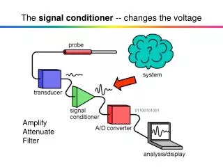
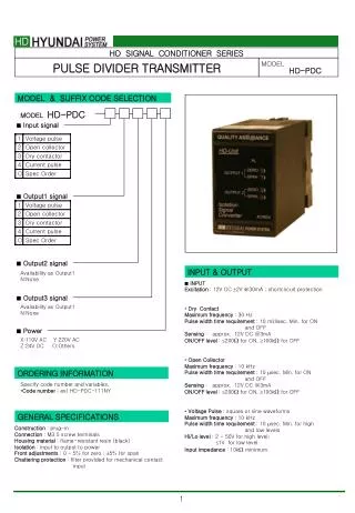
The HD Signal Conditioner Series Pulse Divider Transmitter, model HD-PDC, offers precise signal conditioning capabilities. It features multiple input and output signal options, including voltage pulses, open collector, and dry contact signals. With various power options available, this model provides flexibility in signal processing. The HD-PDC is easy to install with front adjustments for zero and span, and chattering protection filters. It offers reliable performance with low frequency open collector, open collector, voltage pulse outputs, and mercury relay contacts. Order your HD-PDC today for efficient signal division and transmission across different applications.

E N D
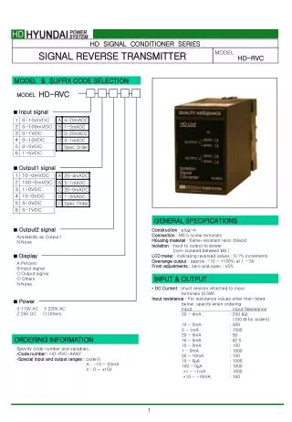
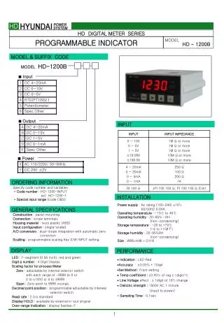
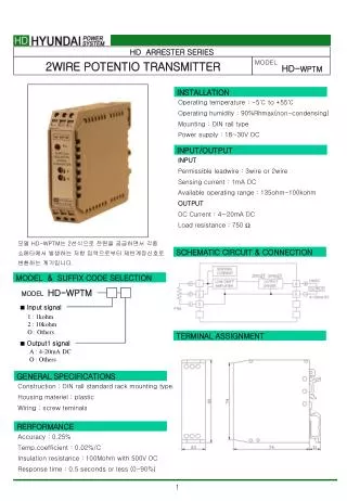
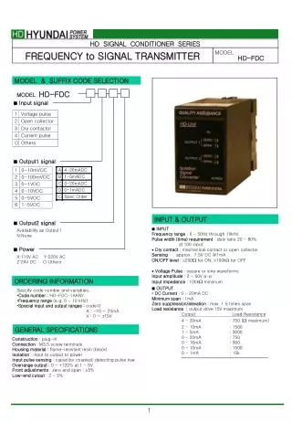
HD SIGNAL CONDITIONER SERIES PULSE DIVIDER TRANSMITTER MODEL HD-PDC MODEL & SUFFIX CODE SELECTION HD-PDC MODEL • Input signal • Output1 signal • Output2 signal INPUT & OUTPUT Availability as Output1 N:None • INPUT Excitation : 12V DC 2V @30mA ; shortcircuit protection • Dry Contact Maximum frequency : 30 Hz Pulse width time requirement : 10 millisec. Min. for ON and OFF Sensing : approx. 12V DC @3mA ON/OFF level : 200 for ON, 100k for OFF • Open Collector Maximum frequency : 10 kHz Pulse width time requirement : 10 sec. Min. for ON and OFF Sensing : approx. 12V DC @3mA ON/OFF level : 200 for ON, 100k for OFF • Voltage Pulse : square or sine waveforms Maximum frequency : 10 kHz Pulse width time requirement : 10 sec. Min. for high and low levels Hi/Lo level : 2 - 50V for high level; 1V for low level Input impedance : 10k minimum • Output3 signal Availability as Output1 N:None • Power X:110V AC Y:220V AC Z:24V DC O:Others ORDERING INFORMATION Specify code number and variables. • Code number : ex) HD-PDC-111NY GENERAL SPECIFICATIONS Construction : plug-in Connection : M3.5 screw terminals Housing material : flame-resistant resin (black) Isolation : input to output to power Front adjustments : 0 - 5% for zero ; 5% for span Chattering protection : filter provided for mechanical contact input
INSTALLATION • OUTPUT • Low Frequency Open Collector : 50V DC @100mA (resistive load) Maximum frequency : 30 Hz Timer : limits ON time within 75 25 millisec. for wider than 75millisec. pulse Saturation voltage : 0.5V DC • Open Collector : 50V DC @50mA (resistive load) Maximum frequency : 10 kHz Saturation voltage : 0.5V DC • Voltage Pulse Maximum frequency : 10 kHz High level : rating (5, 12 or 24V) 10% Low level : 0.5V Load resistance : 250 minimum for 5V; 600 minimum for 12V; 1200 minimum for 24V • Mercury Relay Contact : 132V AC @200mA (cos=1) 264V AC @100mA (cos=1) 30V AC @200mA (resistive load) 100V AC @60mA (resistive load) Maximum frequency : 30 Hz Timer : limits ON time within 75 25 millisec. for wider than 75millisec. pulse Relay life : 5 108 cycles (mechanical) 5 107 cycles (electrical) Power input AC : 85 - 132V, 47 - 66Hz, approx. 2VA DC : rating 10% (ripple 10% p-p max.) approx. 2W (80mA at 24V) Operating temperature : -5 to +60℃ (23 to 140℉) Operating humidity : 30 to 90% RH (non-condensing) Mounting : surface or DIN rail Dimensions : W50 H80 D132 mm See General Spec. Sheet Page B-1. Weight : Terminal assignment : See General Spec. Sheet Page B-1. PERFORMANCEin percentage of span Accuracy : 0.1% Temp. coefficient : 0.02%/℃ (0.01%/℉) Ripple : 0.25% p-p max. (100/120Hz) Response time : 0.4(400ms) seconds (0 - 90%) approx. 25 milliseconds with option Line voltage effect : 0.1% over voltage range Insulation resistance : 100MΩ with 500V DC Dielectric strength : 1500V AC @1 minute (input to output to power to ground) Surge withstand Voltage : 1.2/50sec, 5KV (INPUT to OUTPUT to GROUND) B SCHEMATIC CIRCUITRY & CONNECTION DIAGRAM