
Why the Outfall?
E N D
Presentation Transcript
Protecting the Harbor/Bays Ecosystem 1. Cleaner effluent through source reduction and secondary treatment 2.Dilution 3. Monitoring and Contingency Planning
Outfall Siting Siting process began in 1986. Minimum requirements were set by EPA: • Initial dilution of 50 • More than one tidal cycle away from shoreline • Avoid sensitive and unique resources • Harbor site ruled out
Outfall Siting Process: Siting Criteria Siting criteria developed by Facilities Planning Citizens Advisory Committee: • Attain compliance with state and federal water quality criteria • Protection of commercial on-the-water activities • Maintenance and enhancement of aesthetics • Avoidance of areas of important habitat
Outfall Siting Process: Technical Analysis 7 potential sites evaluated independently by EPA and MWRA: Broad Sound to a location 10 miles offshore • Siting studies in 1987 and 1988 • Engineering and modeling • 2 years of oceanographic sampling including biological, physical and chemical studies
Outfall Siting Process: Site Selection After extensive regulatory review and public comment, 9.5-mile site selected. FEIS determined that: • Water depth and current patterns promote effective dilution • Least likely to affect sensitive resources • Feasible to construct
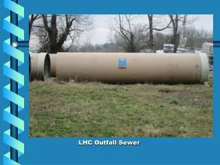
Outfall Design: Tunnel and Risers • 380 feet drop shaft from plant • 9.5 mile tunnel, bored through bedrock • Diffuser system (55 risers each with 8 ports) along final 1.25 miles provide maximum dilution
Outfall Design: Scale Model • Roberts scale model of outfall and diffuser system used to test different port configurations. • 8 ports gave most effective, rapid dispersion.
Outfall Design: Diffuser Head Diffuser head ready for installation
Dilution: Harbor Location • Average depth about 30 feet • Available dilution is about 14 to 1. • With onshore winds, effluent can reach the shoreline. • Effluent plumes reach the surface and are visible. • Effluent is flushed to Massachusetts Bay in a surface plume.
Dilution: Model Harbor Outfalls USGS-Hydroqual model • 77 square miles <200-fold • Lower dilution contours extend along shoreline south of Boston • Parts of CCB shoreline 600-1000.
Dilution: Bay Outfall • Average depth about 100 feet • 1.25 mile diffuser system provides effective dispersion. • Available dilution is about 150 to 1. • Effluent is more than one tidal cycle away from shoreline. • Circulation is greater and more variable than in Harbor, providing better mixing.
Dilution: Model Bay Outfall USGS-Hydroqual model • 3 square miles <200 • Harbor and South Shore 400-600. • Most of MB and all of CCB >1000
Bay Outfall: Mixing in Winter • Water column is well-mixed. • Freshwater effluent plume rises rapidly, and mixes to same density as seawater within a few tens of meters.
Bay Outfall: Mixing and Stratification in Summer • Water column stratification traps effluent below pycnocline (about 15m below the surface). • Nutrients less available to phytoplankton at surface, where there is the most light.
Outfall Benefits: Less Chlorine Use • Chlorine disinfection necessary to protect public health; minimizing chlorine use is environmentally beneficial. • Disinfection effectiveness, K, depends on concentration of chlorine, C, and duration of exposure, t : K = Ct. • Length of outfall increases t, allowing less chlorine use.
CSO/System Master Plan andWet Weather Hydraulic Flow Capacity • Size of treatment plant, interceptors, pumping, CSO facilities integrated in MWRA’s CSO/System Master Plan. • Maximum plant pumping (and new outfall) capacity = 1270 MGD. • New outfall is necessary to achieve levels of CSO control in Plan.
CSO/System Master Plan andWet Weather Hydraulic Flow Capacity • Two existing major Harbor outfalls maximum capacity = 400 MGD. (MWRA average = 370 MGD) • Flows >400 MGD activate two shoreline emergency outfalls in Winthrop Bay; total capacity ~1000 MGD. • At flows >1000 MGD headworks must restrict flow, increasing combined sewer overflows. • New outfall will provide hydraulic capacity of 1270 MGD.
Protecting Resources in the Harbor/Bays Ecosystem • Outfall-diffuser system designed to maximize dilution and mixing. • Benefits Harbor and Bay ecosystem. • Monitoring and Contingency Planning to detect outfall-related impacts and link findings to action plan.