Download
1 / 18
180 likes | 206 Views
Explore cutting-edge research from CERN on optimal undulator and wiggler designs at ANKA, detailing advanced simulation techniques and innovative shimming methods for precise field corrections.

E N D
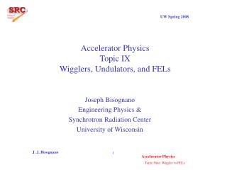
Peter Peiffer, CLIC workshop '08, CERN 3D calculations of undulators and wigglers new projects at ANKAand a novel shimming method Peter Peiffer for A. Bernhard, R. Rossmanith, D.Wollmann and the ANKA collaboration
Peter Peiffer, CLIC workshop '08, CERN ANKA Beam energy 2.5 GeV Stored current 200 mA, Life time 20 hrs Hor. Emittance 40 nm Circumference 110.4 m
Peter Peiffer, CLIC workshop '08, CERN Various projects at ANKA • SCU14 running since 2005 • Planned SCU-s • SCU15 (2009) • SCUW (2010) • SCU2 • Shimming (field error correction) • Classical in-gap • Induction shimming • Calculation tasks • General magnetic design • Optimize dimensions etc. • End period matching • Most challenging: SCUW • Mechanical deviations • Shimming
Peter Peiffer, CLIC workshop '08, CERN Software used Magnetic calculations and general design: Vectorfields Opera 3D (finite element calculation) Advantages: very versatile, various specialized solvers for different tasks (here mostly static and dynamic magnetic solvers are used), both GUI and script controlled, relatively fast. Disadvantages: expensive, many licenses required, resource hungry but not multi-processing capable Other software used: Spectra, Radia and Matlab
Peter Peiffer, CLIC workshop '08, CERN How to model undulators and wigglers Mock up with end period matching z • Simplifications: • coils as 'racetracks' • create reduced model body with suitable boundary conditions • e.g. for end period matching: thin (but not too thin) central slice. y x
Peter Peiffer, CLIC workshop '08, CERN How to model undulators and wigglers Mock up with end period matching z y x • Or, for parameter optimization: • exploit symmetry and create only one full period. (corresponds to infinitely long, ideal undulator)
Peter Peiffer, CLIC workshop '08, CERN Meshing Mesh control: fine mesh: in beam plane on edges and material borders intermediate mesh: in iron body rough mesh: in background far from field sources
Peter Peiffer, CLIC workshop '08, CERN SCUW Undulator mode • Super-Conductive • Undulator / Wiggler • Two independent circuits • 'red' circuit: • fixed current direction • 'yellow' circuit: • current direction switchable • → three grooves with identical • current direction • → period tripling Wiggler mode Calculated brilliance Other Project: Planar/Helical Undulator = undulator with switchable polarization of emitted light
Peter Peiffer, CLIC workshop '08, CERN Mechanical deviationsand trajectory errors Mechanical errors • Field errors influence particle trajectory. • For a fully transparent wiggler the first and second field integral have to vanish. • Errors have to be corrected • (even more crucial for undulators – phase requirement) • Shimming Not shown: period length errors Error contributions from iron and coils scale differently with current. → at least two independent (active) shimming systems needed.
Peter Peiffer, CLIC workshop '08, CERN Error type examples Uncorrected field and difference to an ideal field for a pole height error Uncorrected field and difference to an ideal field for a coil position error
Peter Peiffer, CLIC workshop '08, CERN correction field Classical Shimming • Integral correctors: • overall correction of electron trajectory • transparency of the undulator/wiggler • but no local control of field quality • local correction of field errors • space needed in gap • increased gap or • decreased beam stay clear
Peter Peiffer, CLIC workshop '08, CERN Induction shimming Details published in PhD thesis by D. Wollman Starting idea: in an ideal undulator the integral over one full period vanishes. 3/2 periods: 2 overlapping coils. • Superconductive loop over one period • Enclosed flux = 0 in the ideal case • In presence of field errors, flux ≠ 0 • Faraday's law: current is induced in a closed loop such that the change of flux enclosed by the loop is compensated. • → induced current generates field that exactly counteracts the field error Generalization (n+1)/2 periods: n coils.
Peter Peiffer, CLIC workshop '08, CERN Induction shimmingcalculation Field comparison Modelling: Overlapping pair-wise connected ideal conductors First field integral ...over the full undulator length
Peter Peiffer, CLIC workshop '08, CERN Induction shimmingExperiment 2x 330 nm thick YBCO structures on sapphire substrates (0.5 mm) separated by thin capton foil. YBCO protected by gold layer 7 closed loops total (3 + 4) Each loop: 14x44 mm, conductors 1 mm and 10 mm wide. Mounted on a mock up coil and tested in a LHe cryostat for magnetic measurements (CASPER at FZK)
Peter Peiffer, CLIC workshop '08, CERN Induction shimmingTest setup Induction shimming system mounted on mock up. Center plane of system 1 mm away from pole faces 3 Hall probes mounted on test sled moving on rails, 8 mm away from pole faces.
Peter Peiffer, CLIC workshop '08, CERN Induction shimmingExperimental results Difference between corrected and uncorrected field Uncorrected field and field with correction coils green: position of cc system
Peter Peiffer, CLIC workshop '08, CERN Experimental resultscontinued Correction at different currents First field integral (70 A) • Up to 160 A (485 kA/mm²) induced in correction coils. • Caveat: if cc saturates, hysteresis effects occur • But errors in a real device will be >1 order smaller • so in spite of higher total fields the induction shimming • system will be sufficient even in the current layout.
Peter Peiffer, CLIC workshop '08, CERN Conclusions • 3D calculations: • Opera3D is a very powerful tool with a multitude of possible tasks. • (static and dynamic magnetic properties, forces, heat distribution, quenches, particle tracks etc.) • Note to other Opera users: use latest version (12.027) ! • ANKA schedule: • SCU15 will be installed some time 2009 • SCUW will follow one year later • Stay tuned! Exciting projects are upcoming. • Induction shimming: • Works! • Easier to use than regular shimming • Needs no additional feed-through • Reduced heat load • However: reduced beam-stay-clear • Work on substrate thickness ongoing