Download

1 / 30
300 likes | 444 Views
Polarimetry of Polarized Positrons K. Peter Schuler. R&D polarimetry at or near source energies (5-50 MeV) Low-Energy Positron Polarimetry general choices and considerations Basics of the Transmission Method for photon polarimetry for positron polarimetry

E N D
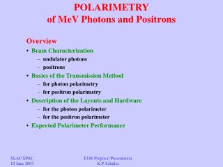
Polarimetry of Polarized PositronsK. Peter Schuler R&D polarimetry at or near source energies (5-50 MeV) Low-Energy Positron Polarimetry general choices and considerations Basics of the Transmission Method for photon polarimetry for positron polarimetry Positron Polarimetry at E166 photon polarimeter for the positron polarimeter Expected Polarimeter Performance operational polarimetry at medium energies (5 GeV) Bhabha & two-photon annihilation dedicated polarimetry for physics data at ILC energies (45.6-500 GeV) Compton laser backscattering (upstream & downstream) and maybe occasional Bhabha cross checks with iron foils collider detector based polarimetry(Ecm = 500-1000 GeV) Bhabha & two-photon annihilation electro-weak processes, such as single W-production Workshop on Positron Sources for the ILC Daresbury, 11-13 April 2005 Polarimetry of Polarized Positrons K. Peter Schüler
Spin-Dependent Processes at Low Energy • e+X e+X Mott scattering • e+e– e+e– Bhabha scattering • e+e– (e+e–)* positronium formation & decay • e+e– annihilation in flight • e+ e+Compton laser backscattering • e+X X brems. ) e+ reconversion and subsequent e– e– • e+e– annih. ) Comptonscattering on pol. e– in 2-step process • both collision partners need to be polarized, except for Mott scattering • (spin-orbit effect), positronium polarimetry (magn. field) and bremsstr. • primary interest is in longitudinal source polarization and polarimetry • Mott polarimetry requires spin rotator (transverse spin effect) • viability and technique for polarimetry depends greatly on • - the analzing power of the physical process • - source intensity, time structure, emittance • - beam energy Workshop on Positron Sources for the ILC Daresbury, 11-13 April 2005 Polarimetry of Polarized Positrons K. Peter Schüler
Low-Energy Positron Polarimetry candidate processes considered for E166 • Photons: Compton Scattering on polarized electrons • forward scattering (e.g. Schopper et al.) • backward scattering • transmission method (e.g. Goldhaber et al.) • Positrons: all on ferromagnetic = polarized e– targets • Annihilation polarimetry (e+e– ) (e.g. Corriveau et al.) • Bhabha scattering (e+e– e+e– ) (e.g. Ullmann et al.) • brems/annihilation (e+ ) plus -transmission (Compton) polarimetry principle difficulties of e+ polarimetry: • huge multiple-scattering at low energies even in thin targets • cannot employ double-arm coincidence techniques or single-event counting due to poor machine duty cycle (bunch length ~ ps) • low energies below 10 MeV, very vulnerable to backgrounds conclusion from studies for ATF and E166: • the transmission method is the most suitablemethod for low-energy positron polarimetry for linear collider type polarized positron sources Workshop on Positron Sources for the ILC Daresbury, 11-13 April 2005 Polarimetry of Polarized Positrons K. Peter Schüler
Transmission Polarimetry of(monochromatic)Photons M. Goldhaber et al. Phys. Rev. 106 (1957) 826. all unpolarized contributions cancel in the transmission asymmetry (monochromatic case) Workshop on Positron Sources for the ILC Daresbury, 11-13 April 2005 Polarimetry of Polarized Positrons K. Peter Schüler
Transmission Polarimetry of Photons monochromatic case Analyzing Power: photon spectra from undulator- or Compton-based photon sources are not at all monochromatic: must use integrated numbers or energies: non-monochromatic case Workshop on Positron Sources for the ILC Daresbury, 11-13 April 2005 Polarimetry of Polarized Positrons K. Peter Schüler
Transmission Polarimetry of Positrons 2-step process: • re-convert e+ via brems/annihilation process • polarization transfer from e+ to proceeds in a well-known manner • measure polarization of re-converted photons with the photon transmission method discussed earlier • infer the polarization of the parent positrons from the measured photon polarization experimental challenges: • huge angular distribution of the positrons at the production target: • e+ spectrometer collection & transport efficiency • background rejection issues • huge angular distribution of the re-converted photons • detected signal includes large fraction of Compton scattered photons • requires extensive simulations to determine the effective Analyzing Power formal procedure: Fronsdahl & Überall; Olson & Maximon; Page; McMaster Workshop on Positron Sources for the ILC Daresbury, 11-13 April 2005 Polarimetry of Polarized Positrons K. Peter Schüler
ATF experimental layout Workshop on Positron Sources for the ILC Daresbury, 11-13 April 2005 Polarimetry of Polarized Positrons K. Peter Schüler
E166: Positron Transport System Workshop on Positron Sources for the ILC Daresbury, 11-13 April 2005 Polarimetry of Polarized Positrons K. Peter Schüler
E166 Positron Beam Simulation distributions behind the converter target (0.5 r.l. Ti) Workshop on Positron Sources for the ILC Daresbury, 11-13 April 2005 Polarimetry of Polarized Positrons K. Peter Schüler
Positron Transport System Workshop on Positron Sources for the ILC Daresbury, 11-13 April 2005 Polarimetry of Polarized Positrons K. Peter Schüler
Analyzer Magnet g‘ = 1.919 0.002 for pure iron Scott (1962) Error in e- polarization is dominated by knowledge in effective magnetization M along the photon trajectory: active volume Photon Analyzer Magnet: 50 mm dia. x 150 mm long Positron Analyzer Magnet: 50 mm dia. x 75 mm long Workshop on Positron Sources for the ILC Daresbury, 11-13 April 2005 Polarimetry of Polarized Positrons K. Peter Schüler
Analyzer Magnet Workshop on Positron Sources for the ILC Daresbury, 11-13 April 2005 Polarimetry of Polarized Positrons K. Peter Schüler
CsI Calorimeter Detector Crystals: from Kharkov Number of crystals: 3 x 3 = 9 Cross section (each crystal): 6 cm x 6 cm Length: 28 cm Density: 4.53 g/cm³ Rad. Length 8.39 g/cm² = 1.85 cm Mean free path (5 MeV): 27.6 g/cm² = 6.1 cm No. of interaction lengths (5 MeV): 4.92 Long. Leakage (5 MeV): 0.73 % Photodiode Readout (2 per crystal): Hamamatsu S2744-08 with preamps Workshop on Positron Sources for the ILC Daresbury, 11-13 April 2005 Polarimetry of Polarized Positrons K. Peter Schüler
Detector Shielding Workshop on Positron Sources for the ILC Daresbury, 11-13 April 2005 Polarimetry of Polarized Positrons K. Peter Schüler
Detector Shielding Workshop on Positron Sources for the ILC Daresbury, 11-13 April 2005 Polarimetry of Polarized Positrons K. Peter Schüler
Spin-Dependent Compton Scattering (employed in Monte Carlo simulation) Workshop on Positron Sources for the ILC Daresbury, 11-13 April 2005 Polarimetry of Polarized Positrons K. Peter Schüler
Simulation based on modified GEANT code which correctly describes the spin-dependence of the Compton process Expected Positron Polarimeter Performance Photon Spectrum & Angular Distr. number & energy-weighted Analyzing Power vs. Energy 10 Million simulated e+ per point & polarity on the re-conversion target Workshop on Positron Sources for the ILC Daresbury, 11-13 April 2005 Polarimetry of Polarized Positrons K. Peter Schüler
Expected Positron Polarimeter Performance Table 13 Workshop on Positron Sources for the ILC Daresbury, 11-13 April 2005 Polarimetry of Polarized Positrons K. Peter Schüler
High-Energy Compton Polarimetry cross sections, spin asymmetry, scattering angles - 1 < P < + 1 - 1 < < + 1 Workshop on Positron Sources for the ILC Daresbury, 11-13 April 2005 Polarimetry of Polarized Positrons K. Peter Schüler
laser choices & parameters • Q-switched Nd:YAG laser • pro very high pulse energy (up to several 100 mJ), • robust commercial systems, relatively low cost • con very low rep-rate (~5 Hz), i.e. only a small sampling fraction (1/2820) • of all ILC bunches can be measured; • inefficient due to long pulse length (ns‘s) • 2.TESLA TTF rf-gun type Nd:YLF laser • pro pulse pattern matched to ILC bunch & pulse structure; • 100% of all ILC bunches will be measured; • high efficiency due to short pulse length (10 ps); • sufficient pulse energy (10-100 J) to achieve negligible stat. errors in 1 sec ! • con non-commercial system, ~ 400 k€ per laser • Pulsed Fabry-Perot Cavity (R&D project at Orsay) • pro aims for similar performance as (2) • con must operate complex laser system remotely in ILC tunnel (reliability!); • feasibility must still be demonstrated (note: HERA Fabry-Perot is not pulsed!) Workshop on Positron Sources for the ILC Daresbury, 11-13 April 2005 Polarimetry of Polarized Positrons K. Peter Schüler
Laser for TTF injector gun regen. multi-stage Nd:YLF ampl. (built by Max-Born-Inst.) operates at nominal pulse & bunch pattern of TESLA S. Schreiber et al. NIM A 445 (2000) 427 t = 8 ps Workshop on Positron Sources for the ILC Daresbury, 11-13 April 2005 Polarimetry of Polarized Positrons K. Peter Schüler
V. Gharibyan, N. Meyners, K.P. Schüler, www.desy.de/~lcnotes/notes.html, LC-DET-2001-047 Tesla design • minimal space & no special magnets • need to change laser wavelength • to UV for z-pole running Workshop on Positron Sources for the ILC Daresbury, 11-13 April 2005 Polarimetry of Polarized Positrons K. Peter Schüler
Specific Polarimeter Studies B. downstream polarimeter study (SLAC) low-energy Compton electrons will be well-separated from disrupted beam (for 20 mrad linac crossing angle!) 4-magnet chicane with 2nd beam focus and laser crossing at center of chicane for details: M. Woods and K.C. Moffeit, SLAC-PUB-10669, Aug. 2004, and K.C. Moffeit, this workshop Laser: 532 nm, 100 mJ, 2 ns FWHM, 5 Hz, 100 m spot size, 11.5 mrad beam crossing angle Workshop on Positron Sources for the ILC Daresbury, 11-13 April 2005 Polarimetry of Polarized Positrons K. Peter Schüler
K. Moffeit, M. Woods, W. Oliver (see ILC MDI workshop at SLAC, Jan. 2005) Chicane Design • essential for downstream polarimetry (separates Compton • electrons from low-energy disrupted beam background), • but adventageous also for upstream polarimetry • requires ~ 50 meters length • same B-field at Z-pole, 250 GeV and 500 GeV running • good acceptance of Compton spectrum at all energies • without changing laser wavelength • laser crossing (Compton IP) at mid-chicane Workshop on Positron Sources for the ILC Daresbury, 11-13 April 2005 Polarimetry of Polarized Positrons K. Peter Schüler
4-Magnet Chicane: general layout Workshop on Positron Sources for the ILC Daresbury, 11-13 April 2005 Polarimetry of Polarized Positrons K. Peter Schüler
(see talk of W. Oliver, MDI workshop, SLAC, Jan. 2005) Chicane properties x x Xmax = 4 w0 pT L / m² position of Compton edge is independent of beam energy e.g. Xmax = 17.8 cm for w0 = 2.33 eV, PT = 0.25 GeV/c, L = 20 m Workshop on Positron Sources for the ILC Daresbury, 11-13 April 2005 Polarimetry of Polarized Positrons K. Peter Schüler
movable laser beam Workshop on Positron Sources for the ILC Daresbury, 11-13 April 2005 Polarimetry of Polarized Positrons K. Peter Schüler
Electron Detector • design similar to gas Cerenkov employed in SLD Compton polarimeter • C4F10 gas (~10 MeV threshold) • detector will be immune against low-energy and diffuse background (syn. rad.) • do not need explicit preradiator, due to high intrinsic event flux (less cross talk) • 20 channels, 10 mm wide each, will cover a large fraction of the Compton spctr. • Emax / E0 = 85%; 50%; 33% at E0 = 45.6; 250; 500 GeV (with xmin = 20 mm) Workshop on Positron Sources for the ILC Daresbury, 11-13 April 2005 Polarimetry of Polarized Positrons K. Peter Schüler
some simulation results I results input parameters 0.5 x 10^6 no. of Compton evt‘s per polarity 676749. random seed 2.33 laser photon energy (eV) 250. electron energy (GeV) 10. crossing angle (mrad) 1.50 luminosity (10^32 / cm² / sec) 0.250 chicane transv. mom. kick (GeV/c) 2. magnet length (m) 20. cntr. dist. magnets 1&2 (3&4) (m) 10. cntr. distance magnets 2&3 (m) 0.7 dist. mag. 4 edge to det. ch. n (m) 20 no. of det. channels (max. 100) 10. det. channel x-size (hor.) (mm) 20. det. channel y-size (vert.) (mm) 150. det. channel length along z (mm) 20. distance det. ch. 1 to beam (mm) 50. z-dist. btw. det. channels (mm) 1. meas. time for stat. error (sec) 0.80 beam pol. to calculate stat. error E0 = 250 GeV w0 = 2.33 eV (green laser) L = 1.5 x 1032/cm²/sec Ch. # x [mm] N+ N- A Rate*A² Rate [MHz] dP/P [%] 1 25 60,682 23,368 -0.444 0.337 1.710 0.228 2 35 45,868 17,348 -0.451 0.262 1.287 0.260 3 45 35,673 16,012 -0.380 0.152 1.052 0.335 4 55 28,337 16,029 -0.277 0.069 0.903 0.486 5 65 22,996 16,956 -0.151 0.019 0.813 0.924 6 75 18,333 17,876 -0.013 0.000 0.737 11.521 7 85 15,248 18,744 0.103 0.007 0.692 1.466 8 95 12,025 19.818 0.245 0.039 0.648 0.646 9 105 9,881 20,480 0.349 0.075 0.618 0.473 10 115 7,815 21,525 0.467 0.130 0.597 0.370 11 125 6,246 21,961 0.557 0.178 0.574 0.324 12 135 4,849 22,795 0.649 0.237 0.562 0.289 13 145 3,479 23,315 0.740 0.299 0.545 0.266 14 155 2,385 23,821 0.818 0.357 0.533 0.250 15 165 1,346 24,171 0.895 0.416 0.519 0.238 16 175 457 20,900 0.957 0.398 0.435 0.249 17 185 0 0 18 195 0 0 19 205 0 0 20 215 0 0 overall stat. error: dP/P = 0.082% for dT = 1 sec Workshop on Positron Sources for the ILC Daresbury, 11-13 April 2005 Polarimetry of Polarized Positrons K. Peter Schüler
Summary Upstream polarimeter study (DESY): • assumes suitable magnetic bend (~ 1 mrad) with dog-leg or chicane geometry • custom-built laser system (similar to existing facility at DESY) with pulse pattern matched to ILC bunch structure (14 100 per sec) • very fast, robust facility, precision of P/P ~ 0.25% Downstream polarimeter study (SLAC): • Assumes 20 mrad linac crossing angle with suitable magnetic chicane • commercial laser system (similar to SLD polarimeter laser) which samples fraction of ILC bunches (5 per sec) • Low-energy Compton electrons are well-separated from disrupted beam background, precision of P/P ~ 0.25% New upstream chicane design: • Still in progress, looks quite promising Workshop on Positron Sources for the ILC Daresbury, 11-13 April 2005 Polarimetry of Polarized Positrons K. Peter Schüler