Download
1 / 23
230 likes | 348 Views
This paper discusses the concept of a polarized positron source utilizing a picosecond CO2 laser pulse within a ring cavity. Through Compton scattering, the laser interacts with a counter-propagating electron pulse, producing γ-quanta. Key parameters such as pulse duration, energy, and frequency are optimized for enhanced γ-yield compared to conventional systems. The study encompasses simulation results, pulse dynamics, and early tests of the Linac Compton Source (LCS). The potential for achieving high-efficiency positron generation to meet future collider demands is highlighted.

E N D
Compton Linacfor Polarized Positrons V. Yakimenko, I. Pogorelsky, M. Polyanskiy, M. Fedurin BNL CERN, October 15, 2009
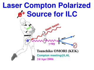
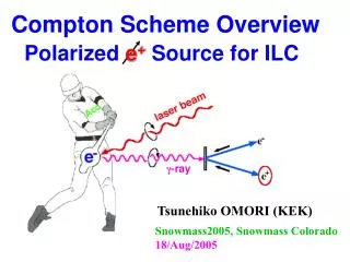
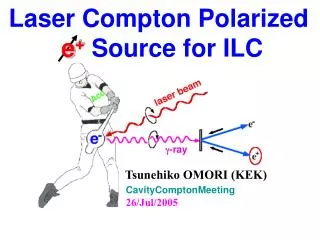
Polarized positron source: the concept - A picosecond CO2 laser pulse circulates in a ring cavity - At each pass through the cavity the laser pulse interacts with a counter-propagating electron pulse generating γ-quanta viaCompton scattering - Optical losses are compensated by intracavity amplifier - The λ-proportional number of photons per Joule of laser energy allows for higher γ-yield (compared to solid state lasers) CO2amplifier Metallic target Interaction point Pulse duration: 5 ps Pulse energy: 1J Repetition: 3-12 ns Pulses/bunch: 100
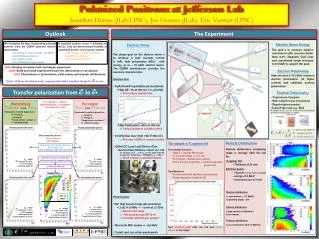
Polarized positron source to e+ conv. target 60MeV beam 6GeV e- beam 30MeV e+ beam ~2 m 3% over 1 s Conventional Non-Polarized Positrons: Polarized γ-ray beam is generated in the Compton back scattering inside optical cavity of CO2 laser beam and 6 GeV e-beam produced by linac. First tests of the laser cavity
Computer simulations: Model Beam Propagation (diffraction, optics, losses) Amplification & Rotational relaxation (fast time-scale) Vibrational relaxation (slow time-scale) Boltzmann equations (discharge energy distribution) Discharge dynamics Pumping (slow time-scale) Spectra (amplification band) Using data from HITRAN2008
Simulation results O16:O18 = 50:50 Natural CO2 Pulse energy dynamics
Simulation results O16:O18 = 50:50 Natural CO2 Pulse energy dynamics Gain spectra
Simulation results O16:O18 = 50:50 Natural CO2 Pulse energy dynamics Pulse spectra (initial and after reaching 1 J)
Simulation results Natural CO2 O16:O18 = 50:50 Pulse energy dynamics Pulse spectra (initial and after reaching 1 J) Temporal pulse profile (initial and after reaching 1 J)
Pulse diagnostics Diffractive grating Pyrocamera Mixing crystal Pyrocamera Filter Streak camera CO2 10μm 1.3 cm-1 0.8 μm Measured Simulated Laser diode 0.9 μm wavenumber 25 ps Measured Simulated time “Streak camera” “Spectrometer” “Interferometer” Fourier transform Δt = 0 5 ps 10 ps Individual pulse Fourier transform Total bandwidth <=> Individual pulse sub-ps resolution Individual lines <=> Train resolution improvement needed 25 ps 50 ps 75 ps Train :) Single-shot :) Simple = reliable :)Indiv. pulse measurements ... Train measurements (?) :( Indirect method :( Multiple-shot :)Indiv. pulse measurements :) Train measurements :( Complicated data analysis :) Single-shot :( Low resolution (~10 ps ) :) Train measurements
Possible configuration with 5 IPs and 1 laser amplifier ~15 cm ~1m
Wall plug power consideration • ILC: • 3 1014 positrons/second; • 2% g - > e+ efficiency for 60 MeVg => 150 kW g beam • Wall plug to g for warm linac/CO2 is expected ~5-10%
Positron generation efficiency normalized by emittance and gamma beam power
Positron generation efficiency normalized by transverse phase space
Positron generation efficiency normalized by transverse phase space and gamma beam power
Conclusion • Polarized positron beam requirement for CLIC can be satisfied with Compton CO2/LINAC based gamma source • Higher energy gamma beam is preferential for the thermal load on the target • Shorter target is preferential when low emittance after target is needed (CLIC, LeHC …) • Total power consumption should be part of optimization for high positron demands (LeHC) • Amplification in Isotope mixture will be tested shortly at ATF • Seed pulse generation using solid state laser will be tested at ATF in ~year • There is no funding/activity for regenerative cavity test