LO Distribution Subsystem
LO Distribution Subsystem. Wes Grammer NRAO. Outline. Design r equirements Top-level block d iagram Subsystem analysis Component selection P ackaging and cooling Interfaces (mechanical and electronic) Production assembly and test Costing and schedule.

LO Distribution Subsystem
E N D
Presentation Transcript
LO Distribution Subsystem Wes Grammer NRAO EOVSA Preliminary Design Review
Outline • Design requirements • Top-level block diagram • Subsystem analysis • Component selection • Packaging and cooling • Interfaces (mechanical and electronic) • Production assembly and test • Costing and schedule EOVSA Preliminary Design Review
LO Distribution Subsystem Design Requirements and Specifications • Deliver +10 dBmmin. LO power to 1st and 2nd IF mixers in all 15 Downconverter modules, over the specified tuning range • 1st LO (LO1) tuning range: 21.5 – 38 GHz, 0.5 GHz steps • 2nd LO (LO2) output frequency: 21.15 GHz • LO1 frequency switching time: < 1 ms, max. • LO1 and LO2 both externally lockable to a 10 MHz reference (from Timing Gen.) • Assume phase noise, spurious and harmonic output specs for Hittite 40 GHz synthesizer applicable to both LO1 and LO2 • Alternate LO1 source, remotely selectable for each antenna (for subarrays) • Monitor and control (except LO1 synthesizers): • Serial I/O bus, RS-485 signaling, ~1.0-3.5 Mbps asynchronous transfer • Uses the same software protocol as Downconverter • Monitor and control (LO1 synthesizers): • 10/100Base-T Ethernet; SCPI (Agilent) instrument control command protocol • Environment: Indoor, temperature-controlled • MTBF > 10 years, for subsystem elements common to entire array EOVSA Preliminary Design Review
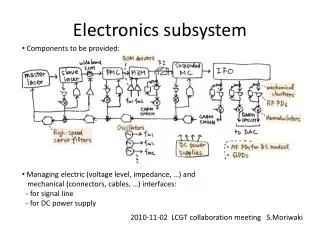
LO Distribution SubsystemBlock Diagram (1) EOVSA Preliminary Design Review
LO Distribution SubsystemBlock Diagram (2) EOVSA Preliminary Design Review
LO System Cascade Analysis • Excel workbooks created to perform stage-by-stage cascaded analysis of the following: • System gain, including mismatch loss • Output power • 1 dB compression point, and output margin • Third-order intercept point (IP3) • Three different distribution configurations were evaluated on performance and cost • LO1 distribution design a challenge, because of higher loss, especially cables, at high frequencies, and additional cascaded components. EOVSA Preliminary Design Review
LO1 Cascade Worksheet EOVSA Preliminary Design Review
LO2 Cascade Worksheet EOVSA Preliminary Design Review
Component Selection • LO1 power amplifier is a single-source item, from Quinstar. • Used modular x15 reference multiplier + PLO for LO2 source instead of a synthesizer, to save cost • Mechanical switch for LO1 has lower loss, higher isolation and better VSWR than PIN diode type. • Marki LO buffer amps have low power dissipation, small size, and are relatively low cost. • Will need lots of flexible cables of various lengths with 2.92mm connectors. Astrolab offers a hand-formable type with low loss, and can be ordered to pre-made custom lengths at a reasonable cost. • As with the Front End and Downconverter, linear power supplies will be used to run all analog electronics EOVSA Preliminary Design Review
Thermal Management • Cooling of LO amplifiers in the Downconverter is not a real issue – dissipation is low. • Conversely, total power dissipation in the LO Distribution Module may be close to 300W: • LO1 power amps each dissipate 60W • LO2 multiplier + PLO dissipate ~13W • LO2 power amplifier dissipates 7W • Linear power supplies with 50% efficiency will dissipate 140W • RF switches are latching self-cutoff type, so average is ~0W. • Solutions: • Use a covered enclosure with a pair of rear-mounted fans to provide continuous flow-through cooling. • Add or design in automatic thermal shutdown protection for the amplifiers and PLO, in case of fan failure. • Make it impossible to power the electronics, unless the fans are on EOVSA Preliminary Design Review
Mechanical Details • Enclosure and Interfaces: • Use a 19” rack-mount 3U or 4U aluminum chassis • LO1 inputs from Hittite synthesizers need to be on the front panel, to keep cables short • All RF outputs on rear panel, on the side closest the Downconverter rack • M&C bus connectors and AC or DC power input on the opposite end of rear panel • Component layout considerations • Good heat sinking of amplifiers, and unobstructed airflow around them • Stacked arrangement for two LO1 splitters, with row of switches in between, to keep cable lengths short and well-matched • Allow for later addition of bi-phase modulators on LO2 outputs EOVSA Preliminary Design Review
LO Distribution Module Interfaces • Hardware: • (16) 2.92mm-M LO1 outputs, to Downconverters • (16) SMA-M LO2 outputs, to Downconverters • (2) 2.92mm-M LO1 inputs, from Hittite sources • (1) BNC-M 10 MHz reference input, from TG • (2) DB-9 or 10-pin RJ-style connectors, M&C I/O • (1) AC fused power entry, IEC style w/switch • Software: • Refer to table in following slide EOVSA Preliminary Design Review
Production Assembly, Testing • Production process steps • Two-port VNA and output power measurements of power amplifiers at all LO frequencies • Bench test of cascaded multiplier + PLO • Assembly and test of LO Distribution Module with RF output cables • Verification of M&C functionality • Test thermal shutdown features • Documentation: Test results, configuration (s/n) list EOVSA Preliminary Design Review
Component Costing, Delivery • All RF components have been specified, and price/delivery quotes received • Reasonable estimates or preliminary pricing on remaining components, except embedded controller • Enclosure and power supply pricing are rough estimates, final TBD • Longest lead times: • LO1 power amplifiers (16 weeks), because of req. NRE • LO2 PLO (10 weeks); semi-custom design EOVSA Preliminary Design Review
Important Schedule Dates for LO Distributor Module • Have all RF components, some cables, and COTS support electronics on order by mid-April at the latest • Complete enclosure fabrication drawings by June 1, send out for quotes, begin fab in mid-June • July 1 – July 15: Order rack, cables, connectors, wire, remaining components for prototype unit construction and site installation • July 1 – August 1: RF component characterization • August – September: Assemble and test prototype module • October 1: Ship prototype to California for installation • Embedded firmware and test software may need to be farmed out, in the interest of saving time. This could happen during July and August, in parallel with assembly. EOVSA Preliminary Design Review