Download
1 / 16
170 likes | 464 Views
Part 1. Implementing Sequential Logic in VHDL. Up and Down Counter with a Seven Segment Display Encoder. S6. S5. S4. S3. S2. S1. S0. DP. Block diagram of the counter. Experiment 2 Problem 1 Pseudo-Random Number Generator. Linear Feedback Shift Register (LFSR).

E N D
Part 1 Implementing Sequential Logic in VHDL Up and Down Counter with a Seven Segment Display Encoder
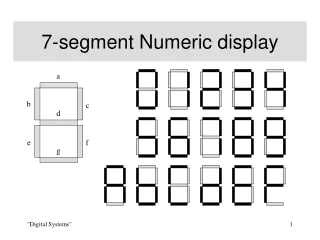
S6 S5 S4 S3 S2 S1 S0 DP
Experiment 2 Problem 1 Pseudo-Random Number Generator
Linear Feedback Shift Register (LFSR) Each stage = D flip-flop L, C(D) Length Connection polynomial, C(D) C(D) = 1 + c1D + c2D2 + . . . + cLDL
Sj-1 Sj-2 Sj-(L-1) Sj-L Initial state [sL-1, sL-2, . . . , s1, s0] LSFR recursion: sj = c1sj-1 c2sj-2 . . . cL-1sj-(L-1) cLsj-L for j L
Example of LFSR 4, 1+D+D4 Length Connection polynomial, C(D) C(D) = 1 + 1D + 0D2 + 0D3 +1D4 c1=1 c2=0 c4=1 c3=0
LFSR State Sequence s4 s3 s2 s1 s0 s4 = c1s3c2s2 c3s1 c4s0 = s3 s0
seed coeff 4 4 load_coeff init_run PRNG strobe ext_clk strobe_divclk 7 current_state
D D D D Q Q Q Q Regular Shift Register Q(1) Q(0) Q(2) Q(3) Sin Clock Enable Hint: Use similar techniques for clocking and enabling LFSR
D D D D Q Q Q Q Initializing Serial Shift Register with Parallel Load Load D(3) D(2) D(1) D(0) Sin Clock Enable Q(3) Q(2) Q(1) Q(0) Hint: Use similar technique for initializing LFSR
Experiment 2 Problem 2 One-Hex-Digit Calculator
operand 4 3 operation code One-hex-digit calculator strobe 7 output
Operations operation_code : operation 1 : ADD 2: SUB 4: AND 5: OR 6: XOR 7 : MUL (bonus)
Sequence of actions a. display output blank b. operation code read and displayed on a seven segment display c. operand 1 read and displayed on a seven segment display d. operand 2 read and displayed on a seven segment display e. result calculated and displayed on a seven segment display f. go to step a.