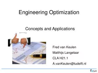
Model-Based Systems Engineering with SysML: Problem Definition, Simulation and Optimization
Model-Based Systems Engineering Center. Model-Based Systems Engineering with SysML: Problem Definition, Simulation and Optimization. Chris Paredis Associate Director Model-Based Systems Engineering Center Georgia Tech chris.paredis@me.gatech.edu. Presentation Overview.

Model-Based Systems Engineering with SysML: Problem Definition, Simulation and Optimization
E N D
Presentation Transcript
Model-BasedSystems EngineeringCenter Model-Based Systems Engineeringwith SysML:Problem Definition, Simulation and Optimization Chris Paredis Associate DirectorModel-Based Systems Engineering Center Georgia Tech chris.paredis@me.gatech.edu
Presentation Overview • Model-Based Systems Engineering • Overview and motivation • The Systems Modeling Language (OMG SysMLTM) • Model Transformation for Simulation and Optimization • System Architecture Exploration • Transforming SysML models into analysis and optimization models
Model-Based Systems EngineeringMoving from Documents to Models Software Manufacturing Analysis ProjectManagement Marketing • Power plant • Transmission • Brakes • Chassis • … CAD
Model-Based Systems EngineeringMoving from Documents to Models Software ImplicitDependenciesbetweenDocuments Manufacturing Analysis ProjectManagement Marketing • Power plant • Transmission • Brakes • Chassis • … CAD
Model-Based Systems EngineeringMoving from Documents to Models Software Manufacturing Analysis ProjectManagement System Model Marketing • Power plant • Transmission • Brakes • Chassis • … CAD
Model-Based Systems EngineeringWhat Kinds of System Models? Requirements Dynamic Performance Structure / Physical Architecture Control Input Power Equations Vehicle Dynamics Engine Transmission Driveline Integrated System ModelMust Address MultipleAspects of a System System Model Behavior / Functional Architecture Start Shift Accel Brake Models are more formal, complete & semantically rich (Adapted from OMG SysML Tutorial)
The Payoff for MBSE Models are more formal, complete & semantically rich • Improved communication less ambiguous, more consistent • Improved complexity management traceability, abstraction, decomposition • Improved design quality more efficient and effective exploration • Improved knowledge reuse integrated model libraries
Summary: Making Better Decision • Goal of MBSE: Improve Efficiency & Rationality • Efficient = Perform the SE process with fewer resources • Rational = Make better decisions with available information (Be consistent with designer’s beliefs and preferences) Knowledge/Beliefs Ideas Preferences Alternatives Outcomes Selection Criterion: E[u] Decision Theory (Figure Adapted from G. Hazelrigg) Maximize E[u] Most PreferredSystem Alternative
Presentation Overview • Model-Based Systems Engineering • Overview and motivation • The Systems Modeling Language (OMG SysMLTM) • Model Transformation for Simulation and Optimization • System Architecture Exploration • Transforming SysML models into analysis and optimization models
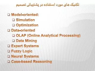
SysML: A Key Enabler for MBSE The Systems Modeling Language (OMG SysMLTM)is a visual, general purpose modeling language • What Can be Expressed in SysML? • All the information and knowledge needed for the application of a systems development methodology • Specification • Analysis • Design • Verification • Validation • Hardware • Software • Data • Personnel • Procedures • Facilities
(Source: Friedenthal, www.omgsysml.org) definition Pillars of SysML — 4 Main Diagram Types 1. Structure 2. Behavior 4. Requirements 3. Parametrics
(Source: Friedenthal, www.omgsysml.org) definition Pillars of SysML — 4 Main Diagram Types 1. Structure 2. Behavior use 4. Requirements 3. Parametrics
(Source: Friedenthal, www.omgsysml.org) use definition Pillars of SysML — 4 Main Diagram Types 1. Structure 2. Behavior interaction 4. Requirements 3. Parametrics
(Source: Friedenthal, www.omgsysml.org) use definition Pillars of SysML — 4 Main Diagram Types 1. Structure 2. Behavior interaction state machine 4. Requirements 3. Parametrics
(Source: Friedenthal, www.omgsysml.org) state machine use definition Pillars of SysML — 4 Main Diagram Types 1. Structure 2. Behavior interaction activity/ function 4. Requirements 3. Parametrics
(Source: Friedenthal, www.omgsysml.org) state machine activity/ function use definition Pillars of SysML — 4 Main Diagram Types 1. Structure 2. Behavior interaction 4. Requirements 3. Parametrics
(Source: Friedenthal, www.omgsysml.org) state machine activity/ function use definition Pillars of SysML — 4 Main Diagram Types 1. Structure 2. Behavior interaction 4. Requirements 3. Parametrics
(Source: Friedenthal, www.omgsysml.org) Cross Connecting Model Elements 1. Structure 2. Behavior 4. Requirements 3. Parametrics
(Source: Friedenthal, www.omgsysml.org) Cross Connecting Model Elements 1. Structure 2. Behavior allocate 4. Requirements 3. Parametrics
(Source: Friedenthal, www.omgsysml.org) Cross Connecting Model Elements 1. Structure 2. Behavior allocate 4. Requirements 3. Parametrics
(Source: Friedenthal, www.omgsysml.org) Cross Connecting Model Elements 1. Structure 2. Behavior allocate satisfy 4. Requirements 3. Parametrics
(Source: Friedenthal, www.omgsysml.org) allocate Cross Connecting Model Elements 1. Structure 2. Behavior satisfy 4. Requirements 3. Parametrics
(Source: Friedenthal, www.omgsysml.org) allocate Cross Connecting Model Elements 1. Structure 2. Behavior value binding satisfy 4. Requirements 3. Parametrics
(Source: Friedenthal, www.omgsysml.org) allocate value binding Cross Connecting Model Elements 1. Structure 2. Behavior satisfy 4. Requirements 3. Parametrics
(Source: Friedenthal, www.omgsysml.org) allocate value binding verify Cross Connecting Model Elements 1. Structure 2. Behavior satisfy 4. Requirements 3. Parametrics
Presentation Overview • Model-Based Systems Engineering • Overview and motivation • The Systems Modeling Language (OMG SysMLTM) • Model Transformation for Simulation and Optimization • System Architecture Exploration • Transforming SysML models into analysis and optimization models
Formal Models + Model Transformations Stage-Gate Documents Transformation Transformation Transformation Project Management Metrics Simulation &Optimization
refers to refers to Source Metamodel Transformation Specification Target Metamodel conforms to executes conforms to reads writes Source Model Transformation Engine Target Model Model Transformation • Transformation Specification isalso a Model automated generation of transformation engine code • Origins • Model Driven Architecture/ Engineering • Tools • MOFLON, QVTo, ATL, GME/GReAT, VIATRA2, Kermeta,… • Example Usages: • Automation of repeatedmodeling patterns • Tool interoperation • Document generation • Consistency checking • Dependency propagation (Czarnecki, K., & Hellen, S., 2006)
SysML-Modelica Transformation SpecificationRepresenting Hybrid Continuous/Discrete Dynamics in SysML • OMG standard for integrating SysML and Modelica • Transformation is specified in QVT (Query/View/ Transformation) – an OMG specification conforms to SysML+SysML4Modelicametamodel conforms toModelicametamodel SysML Tool XMI(SysML4Modelica) XMI(Modelica) Modelica abstract syntax QVT(normative) OMC Tool-Specific Repository Modelica.mo file
SysML-ModelCenter TransformationExecuting SysML Parametric Analyses / Optimizations Transformation • Through ModelCenter, include and executea wide range of engineering analyses in SysML • Trace requirements and design models to analysis System Properties Analysis Model
Presentation Overview • Model-Based Systems Engineering • Overview and motivation • The Systems Modeling Language (OMG SysMLTM) • Model Transformation for Simulation and Optimization • System Architecture Exploration • Transforming SysML models into analysis and optimization models
Architecture Exploration Framework Problem Definition Components SysML SysML GenerateArchitecture Expl. Problem Topology Analysis Variable FidelityModel Selection LinearModels SysML SysML GAMS / AMPL / AIMMS GenerateAlgebraic Design Problem Mixed-IntegNonlin Solver Algebraic Analysis NonlinearModels SysML SysML Design Explorer Monte Carlo + Kriging Modelica GenerateDynamic Design Problem OptimizationSolver Uncertainty Quantification Dynamic Analysis DynamicModels Problem Formulation Problem Solution Transformation
Given: Component models Objectives / preferences Find: Best system architecture Best component parameters (Best controller) engine Excavator pump_vdisp accum v_3way cylinder System Architecture Explorationfor a Hydraulic Excavator How to connect and size these?
Specify Allowable/Required Components A Component may be abstract, representing multiple sub-classes Multiplicities for optional components Specify the required connectors in IBD
Specify Allowable/Required Connections Connectors blank not allowed 1 required + optional + + 1 1 1 1 Note: mock-up – under development
Domain Knowledge: Model Libraries Component Structure Algebraic Linear/Nonlinear DAE — Modelica
Model Transformations to Domain Knowledge • When cylinder is used, other corresponding models are often used also Capture the reuse pattern
Model Transformations to Domain KnowledgeDefining the Reuse Patterns in SysML
Transformation to Mixed Integer (Linear) Program • Composition of component models • Decision variables for component & connector selection Efficient filtering of architecture alternatives System Model Generation of AIMMS – CPLEX models through transformation AIMMS – CPLEX
Step 1: Create a Superstructure All potential components All potential connections
Step 2: Linearization of Constitutive Equations τmax τ(1) τ(2) τ(0) Binary Variable ω τ(3)
Step 3: Generate Connection Equations A C • Kirchhoff’s Laws: • A.flow + flowAC = 0 • B.flow + flowBC = 0 • C.flow – flowAC – flowBC = 0 • A.pressure = B.pressure = C.pressure • When considering optional connections: • A.flow + flowAC * existsAC = 0 • B.flow + flowBC * existsBC = 0 • C.flow – flowAC * existsAC – flowBC * existsBC = 0 • (A.pressure - C.pressure) * existsAC = 0 • (B.pressure - C.pressure) * existsBC = 0 B Model is nonlinear Difficult to solve Continuous Variables Binary Variable
Step 3: Generate Connection Equations A C • Kirchhoff’s Laws: • A.flow + flowAC = 0 • B.flow + flowBC = 0 • C.flow – flowAC – flowBC = 0 • A.pressure = B.pressure = C.pressure • When considering optional connections: • flowAC <= existsAC * upperBound • flowAC >= - existsAC * upperBound • flowBC <= existsBC * upperBound • flowBC >= - existsBC * upperBound B Model is linear Can be solved very quickly
Step 4: Solve Mixed-Integer Linear Equations • Potentially 4 Pumps, 4 Valves, 4 Cylinders, 1 Motor • 4 Motion Phases • Generated MIP Problem: 7147 Constraints & 2175 Variables • Solution time: < 10 minutes
So What? • Express complex problems in domain-specific language • Multiple perspectives, multiple operational phases, … • Transform problem into declarative equations • Efficient formulation much larger problems than can be formulated manually • Efficient solution take advantage of knowledge of the mathematical structure of the equations • Same problem definition can be reused at different levels of abstraction • Goal is NOT to find the optimal solution in one step… but to filter out the poor solutions so that more accurate and more expensive models can be applied selectively
Architecture Exploration Framework Problem Definition Components SysML SysML GenerateArchitecture Expl. Problem Topology Analysis Variable FidelityModel Selection LinearModels SysML SysML GAMS / AMPL / AIMMS GenerateAlgebraic Design Problem Mixed-IntegNonlin Solver Algebraic Analysis NonlinearModels SysML SysML Design Explorer Monte Carlo + Kriging Modelica GenerateDynamic Design Problem OptimizationSolver Uncertainty Quantification Dynamic Analysis DynamicModels Problem Formulation Problem Solution Transformation
Model-BasedSystems EngineeringCenter Key Take-Aways • Model-Based Systems Engineering (MBSE) • Key for meeting tomorrow’s demands on complexity & functionality • SysML • The leading standardized language for supporting MBSE • Formal models enable model transformation • Extract information, documents, analyses from SysML models • Efficient solution of Architecture Exploration Problems • Formal problem definition optimization at different levels of abstraction