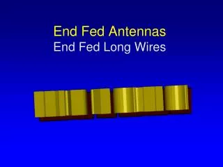
End-Fed Half Wave Antennas: Simple Multiband Wires
340 likes | 394 Views
Learn about the simplest multiband wire antennas, impedance, balancing currents, grounding techniques, and harmonic frequencies.

End-Fed Half Wave Antennas: Simple Multiband Wires
E N D
Presentation Transcript
End Fed Half Wave Antennas Perhaps the Simplest of All Multiband Wire Antennas Hap Griffin WZ4O January 2019
Before We Start…Recall from previous programs and antenna/transmission line theory…In any resonant RF system with standing waves that impedance changes with distance from a source or load and repeats every half wavelength…And…A Half Wavelength away from an open (Hi Z) is an open (Hi Z),and a Quarter Wavelength away from an open (Hi Z) is a short (Lo Z).
Current, Voltage and Impedance on a Half Wavelength Dipole Impedance Voltage Current Ohm’s Law: R = E/I Impedance: Z = R ± X
In a low impedance feedpoint antenna (half wave dipole fed at midpoint, or a quarter wave vertical), we are concerned with current balance…the antenna has to “work against” a stable reference (ground). Balance and Grounding in Low Impedance Antennas In a dipole, the two sides of the antenna provide the reference for each other and the feed current is balanced between the two sides.
In a low impedance feedpoint antenna (half wave dipole fed at midpoint, or a quarter wave vertical), we are concerned with current balance…the antenna has to “work against” a stable reference (ground). Balance and Grounding in Low Impedance Antennas In a ¼ wave vertical, the reference can be the actual “ground”…
In a low impedance feedpoint antenna (half wave dipole fed at midpoint, or a quarter wave vertical), we are concerned with current balance…the antenna has to “work against” a stable reference (ground). Balance and Grounding in Low Impedance Antennas Or, a set of radials (also known as a “counterpoise). For a low impedance feedpoint where we have significant current that has to be carried, the radials are generally ¼ wavelength long to provide a low impedance at their joining point (remember, ¼ wave away from an open is a short).
In a high impedance feedpoint antenna, for any given power, the currents are less and having a stable reference point (ground or counterpoise) becomes less important. Balance and Grounding in High Impedance Antennas
The Zeppelin Antenna No “ground” is available…so a high impedance antenna (a half wavelength wire fed at the end (half wave away from an open is an open)) is used to minimize the need for a ground reference or counterpoise. A ¼ wavelength of transmission line is use to transform the Hi Z of the antenna to Lo Z for the transmitter.
A Modern Day Incarnation of the Classic Zeppelin Antenna… the familiar J-Pole Antenna!
A Modern Day Incarnation of the Counterpoise… The “Tigertail” or “Rat Tail” to enhance the performance of an HT antenna
Current, Voltage and Impedance on a Half Wavelength Dipole Impedance Voltage Current Ohm’s Law: R = E/I Impedance: Z = R ± X
Dipole Operated on 2nd Harmonic Frequency Impedance Voltage Current Ohm’s Law: R = E/I Impedance: Z = R ± X
Dipole Operated on Fundamental and 2nd Harmonic Frequencies Fundamental Impedance 2nd Harmonic Impedance Feedpoint Impedance in the middle is vastly different on fundamental frequency vs 2ndharmonic
Dipole Operated on Fundamental and 2nd Harmonic Frequencies Fundamental Impedance 2nd Harmonic Impedance At a point offset from the middle, the feedpointImpedance is same on fundamental frequency and 2nd harmonic, but is higher than at a center feedpoint.
Dipole Operated on Fundamental and 2nd Harmonic Frequencies w/ Offset Feedpoint Z = Approx 200 ohms Fundamental Impedance 2nd Harmonic Impedance Balun By using a 4:1 balun at the point where the fundamental and 2nd harmonic feedpoint impedances are the same, we have a multiband antenna
Current, Voltage and Impedance on a Dipole Impedance Voltage Current Ohm’s Law: R = E/I Impedance: Z = R ± X
Dipole Operated on 2nd Harmonic Frequency Impedance Voltage Current Ohm’s Law: R = E/I Impedance: Z = R ± X
Dipole Operated on 3rd Harmonic Frequency Impedance Voltage Current Ohm’s Law: R = E/I Impedance: Z = R ± X
Dipole Operated on 4th Harmonic Frequency Impedance Voltage Current Ohm’s Law: R = E/I Impedance: Z = R ± X
Harmonic Relationship of Ham Bands 80m – 3.5 MHz 40m – 7.0 MHz 30m - 10.1 MHz 20m – 14 MHz 17m – 18.068 MHz 15m – 21 MHz 10m – 28 MHz
Takes the place of the ¼ wave transmision line section of the Zepp antenna but is broadbanded.
Grounding the EFHW Antenna Config 1: No ground, use coax shield as counterpoise Works but can have RF in the shack Wire Supported by Any Convenient Means Radio Matching Unit Can be Mounted Close to Ground
Grounding the EFHW Antenna Config 2: Counterpoise wire added Works better than Config 1, may need to adjust length of counterpoise for best VSWR performance Radio Matching Unit Counterpoise
Grounding the EFHW Antenna Config 3: No ground, use coax shield as counterpoise and place RF choke near shack Works better than Config 1 Radio Matching Unit RF Choke
Grounding the EFHW Antenna Config 4: Ground at matching unit Works better than Config2 (Counterpoise) Radio Matching Unit
Grounding the EFHW Antenna Config 5: Ground at matching unit with RF choke near matching unit Best performance in tests Radio RF Choke Matching Unit