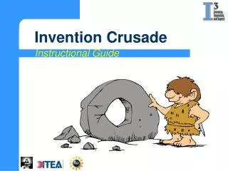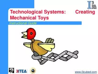
Instructional Guide
This instructional guide leads you through the process of designing a mechanical toy using simple machines and linkage mechanisms. You will explore concepts such as levers, pulleys, and gears while applying the Engineering Design Process. The unit involves identifying design challenges, generating ideas, building prototypes, and testing the toys with peer feedback. You’ll learn to innovate and improve your designs, making them both fun and safe for target age groups. Participate in discussions and presentations to share insights and final designs.


Instructional Guide
E N D
Presentation Transcript
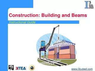
Instructional Guide Technological Systems: Creating Mechanical Toys www.i3cubed.com
During this unit you are going to: • Explore simple machines and linkage mechanisms. • Design a toy that uses simple machines and linkage mechanisms create movement. • Design, build, test and make improvements to your designs.
Simple Machines LEVER WEDGE INCLINED PLANE SCREW WHEEL AND AXLE PULLEY
Class 1 Lever Class 2 Lever Effort Load Fulcrum Class 3 Lever Effort Fulcrum Load Load Effort Fulcrum Levers The fulcrum (pivot) is between the effort and the load. The load is between the effort and the fulcrum (pivot). The effort is between the load and the fulcrum (pivot).
Speed of Driven Gear Speed of Driver Gear x Teeth in Drive Gear = Speed of Driven Gear = x Teeth in Driver Gear 12 = 240 RPM 360 RPM 8 Pulleys and Gears
Mechanisms and Linkages Definitions • Fixed Point - a point that remains stationary, but links can rotate about that point. • Pivot Point - point can move and link can also rotate about the pivot. • Slider - holds links to back and forth movement without rotation. Sliders
Design Challenge You are a toy designer who is familiar with the Engineering Design Process. You have been asked to use this process to design, build, and test a safe toy that incorporates simple machines and linkage mechanisms.
Step 1 – Identify a challenge • What is the design challenge? • What limitations are given? • What are the constraints?
Step 2 – Explore Ideas • Sketch ideas for the new toy. • Refine the best idea and label the parts. √ Identify a challenge
Step 3 – Plan and Develop • Brainstorm ideas for improving the toy. • List the materials that are needed to make the prototype. • Build the prototype. √ Identify a challenge √ Explore Ideas
Step 4 – Testing and Evaluating • Have at least three students test the toy’s operations and record the results. • Ask the students: • Why would this toy be safe or unsafe? • What would be fun about playing with the toy? • What age child would play with the toy and why? √ Identify a challenge √ Explore Ideas √ Plan and Develop
Step 5 – Presenting the Solution • Prepare a presentation containing: • A sketch of the design with all the parts labeled. • The design challenge and design constraints. • A discussion on how the design was developed and tested. • Use of the prototype and how it works. • The feedback from the testers and how your team would redesign. • Answer specific questions. √ Identify a challenge √ Explore Ideas √ Plan and Develop √ Testing and Evaluating
Conclusion • Compare all of the team toys. • Discuss final designs with the class. • Likes and dislikes of toys. • Best design. • Changes that could be made on the toys. • Have students bring in and present toys that include simple machines and have linkages.