SECTION 9 PARAMETERIZATION
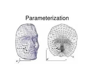
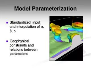
SECTION 9 PARAMETERIZATION. Parameterization. This section explains how Adams/Car models are parameterized, by location and orientation, using hardpoints and construction frames. Parameterization. What’s in this section: Parameterization in Adams/Car Creating Hardpoints

SECTION 9 PARAMETERIZATION
E N D
Presentation Transcript
SECTION 9 PARAMETERIZATION
Parameterization • This section explains how Adams/Car models are parameterized, by location and orientation, using hardpoints and construction frames.
Parameterization • What’s in this section: • Parameterization in Adams/Car • Creating Hardpoints • Creating Construction Frames • Location Parameterization • Orientation Parameterization
Parameterization in Adams/Car • Why parameterize? • Parameterizing a template allows you to build relationships into the model so that when you change a modeling entity, Adams/Car automatically updates all other entities that depend on it. You can, therefore, build a whole vehicle model to depend on only a few key hardpoints and variables, saving time and effort in making design changes. • What can you parameterize? • Location and orientation expressions • Geometry • Group activity • Functions • And so on
Creating Hardpoints • Hardpoints define all key locations in your model. They are the most elementary building blocks that you use to parameterize locations for higher-level entities, such as construction frames, parts, and attachments. Hardpoints are the same as points in Adams/View, except that they are always created on ground by default. • You create hardpoints in Template Builder. To create hardpoints, go to Build Hardpoint New. In the dialog box, specify the name of the hardpoint, if it’s a left, right or single, and the location. When you create a left or right hardpoint, Adams/Car creates a corresponding paired hardpoint by reflecting the location along the car’s longitudinal axis.
Creating Hardpoints (Cont.) • You can modify hardpoints by right-clicking the hardpoint and selecting the hardpoint name followed by Modify. • You can also modify hardpoints by going to Build Hardpoint, where you can select: • Table - Every hardpoint in the model appears and you can enter new locations for all. • Modify - You can modify only one hardpoint at a time.
Creating Construction Frames • Construction frames are building blocks that you use whenever an entity requires that you specify an orientation in addition to a location. Construction frames are the same as markers in Adams/View. • To create construction frames, go to Build Construction Frame New. In the dialog box, specify the name and if it’s a left, right, or single. Define the location and orientation, by selecting one of the following options.
Creating Construction Frames (Cont.) • Location parameterization • Delta location from coordinate • Centered between coordinates • Located on a line • Located along an axis • Location input communicator • Located at flexible body node
Creating Construction Frames (Cont.) • Orientation parameterization • User entered values (Euler angles) • Delta orientation from coordinate • Parallel to axis • Oriented in plane • Orient to zpoint - xpoint • Orient axis along line • Orient axis to point • Orientation input communicator • Toe/camber • Orient about axis
Creating Construction Frames (Cont.) • To modify construction frames, right-click the construction frame and select the construction frame name followed by Modify. • You can also modify construction frames by going to Build Construction Frame Modify. In the dialog box, select the name of the construction frame you want to modify. You can modify the location and orientation.
Location Parameterization • Delta location from coordinate • Locate with respect to a defined reference frame. • You can define X, Y, Z displacement in the local or global coordinate reference frame. Location is 100 length units along global x-axis Global reference frame Coordinate reference
Location Parameterization (Cont.) • Centered between coordinates • Using the two-coordinates method, the entity is located on the mid-point along an imaginary line joining the defined reference coordinates. • Using the three-coordinate method, the entity is located on the center point of a plane defined by the three reference coordinates.
Location Parameterization (Cont.) • Located along an axis • The entity is located a defined distance along the chosen axis of the reference construction frame. • In this example, the entity has been located 100 length units along the z-axis of the reference construction frame.
Location Parameterization (Cont.) • Located on a line • Locates the entity along a line defined by the two reference coordinates. • The entity is located a defined percentage along the line measured from the first reference coordinate to the second reference coordinate.
Location Parameterization (Cont.) • Location input communicator • Locates the entity using location data from the chosen input communicator. • Use this option to locate entities with respect to reference frames in other templates. • At the assembly stage, the location data is communicated to the input communicator from the corresponding output communicator in the other template. Up to that point, the entity is located at the initial value defined in the input communicator.
Location Parameterization (Cont.) • For more information on communicators, see the following KBAs: • Article 9182 -- Use of mount and location communicators at: http://support.mscsoftware.com/kb/results_kb.cfm?S_ID=1-KB9182 • Article 9184 -- Example of use of location communicators at: http://support.mscsoftware.com/kb/results_kb.cfm?S_ID=1-KB9184
Orientation Parameterization • Delta orientation from coordinate • Orients the entity with respect to the reference frame, using the Euler angle orientation defined. • In this example, the entity has been defined such that there is no change in orientation with respect to the reference construction frame.
Orientation Parameterization (Cont.) • Delta orientation from coordinate • Orients the entity with respect to the reference frame, using the Euler angle orientation defined. • In this example, the entity has been rotated -30 degrees about the reference frame z-axis and then 90 degrees about the new x-axis.
Orientation Parameterization (Cont.) • Parallel to axis • Orients the defined axis on the entity parallel to the defined axis on the reference frame. • In this example, the z-axis of the entity is oriented parallel to the negative x-axis on the reference frame.
Orientation Parameterization (Cont.) • Oriented in plane • Orients the z-axis along a line defined by the first and second reference coordinates, and orients the x-axis such that the entities zx plane lies in the plane defined by the three reference coordinates.
Orientation Parameterization (Cont.) • Orient to zpoint-xpoint • Orients the z-axis towards the first reference coordinate and the x-axis towards the second reference coordinate.
Orientation Parameterization (Cont.) • Orients the x-axis towards the first reference coordinate and the z-axis towards the second reference coordinate.
Orientation Parameterization (Cont.) • User-entered values • Orients the construction frame using Euler angles: Z-X’-Z’ incremental rotations with respect to the global construction frame (origo).
Orientation Parameterization (Cont.) • Toe/Camber • Sets the toe and camber orientation. Generally, the toe and camber define the global orientation of the wheel spin axis. You obtain toe and camber values from parameter variables or input communicators.