Download
1 / 26
260 likes | 377 Views
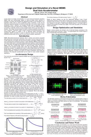
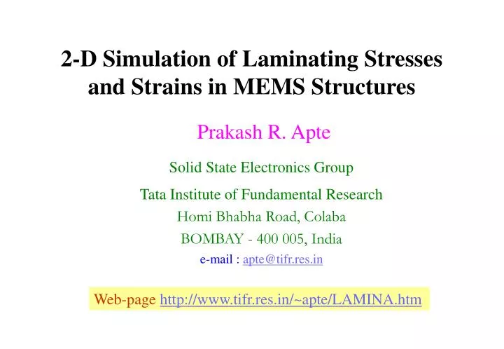
2-D Simulation of Laminating Stresses and Strains in MEMS Structures. Prakash R. Apte Solid State Electronics Group Tata Institute of Fundamental Research Homi Bhabha Road, Colaba BOMBAY - 400 005, India e-mail : apte@tifr.res.in. Web-page http://www.tifr.res.in/~apte/LAMINA.htm. OUTLINE.

E N D
2-D Simulation of Laminating Stresses and Strains in MEMS Structures Prakash R. Apte Solid State Electronics Group Tata Institute of Fundamental Research Homi Bhabha Road, Colaba BOMBAY - 400 005, India e-mail : apte@tifr.res.in Web-pagehttp://www.tifr.res.in/~apte/LAMINA.htm
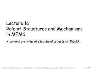
OUTLINE • Laminated Structures in MEMS • 2-D Stress-Strain Analysis for Laminae • Equilibrium and Compatibility Equations • 4th Order Derivatives and 13-Point Finite Differences • Boundary Conditions : Fixed, Simply-Supported • Program LAMINA • Simulation of Laminated Diaphragms : having Si, SiO2 and Si3N4 Layers • Conclusions
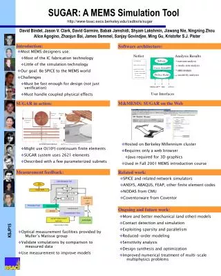
Tensile µn = 950 Si Fused Silica µn = 500 Compressive µn = 250 Si Si Sapphire Silicon 2-Layer Laminated Structures From : Fan, Tsaur, Geis, APL, 40, pp 322 (1982)
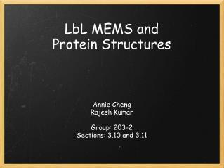
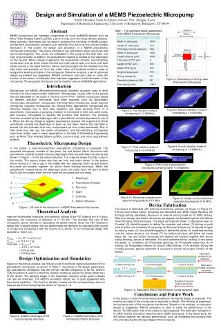
Si3N4 SiO2 Silicon <100>Substrate Thin Diaphragm Multi-Layer Laminated Structures in MEMS
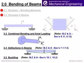
Dr. P.R. Apte: Equilibrium and Compatibility Equations Mxx + 2 Mxy + Myy = -qeff - - - Equi. Eqn. where Mxy are the bending moments qeff = Transverse Loads + In-plane Loads + Packaging Loads =qa + Nx xx + 2Nxyxy + Nyyy + qpack where is the deflection in the transverse direction N are the in-plane stresses
[ ] { } { } Dr. P.R. Apte: Equilibrium and Compatibility Equations 10,yy - 120,xy + 20,xx = 0 - - - Comp. Eqn. where 20,xx a b N = M bT d where [a] , [b] , [d] are 3 x 3 matrices of functions of elastic, thermal and lattice constants of lamina materials
Dr. P.R. Apte: Equilibrium and Compatibility Equations Equilibrium Equations b21 Uxxxx + 2 (b11 - b33)Uxxyy + b12 Uyyyy + d11 xxxx + 2 (d12 - 2d33) xxyy + d22 yyyy = - [ q + Uyyxx + Uxxyy – 2 Uxyxy ] Compatibility Equations a22 Uxxxx + (2a12 - a33)Uxxyy + a11 Uyyyy + b21 xxxx + 2 (b11 - b33) xxyy + b12 yyyy = 0
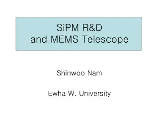
8 7 6 LAMINA with 8 layers 5 4 3 2 1 j o DiaphragmwithMesh or Grid o o o . i , j i o o o o o o o o o 13 - point Formulationof Finite Differencesfor 4th order derivatives Stress- Strain Analysis of Laminated structures
xx 4 1 -2 1 3 11 5 xxxx -4 1 1 -4 6 10 6 2 1 12 9 7 13 1 -2 1 xxyy 8 -2 -2 4 1 1 -2 13 - point Formulationof Finite Differencesfor 4th order derivatives 4th order derivatives inU, Airy Stress function and ,deflection Entries in box/circles are weights
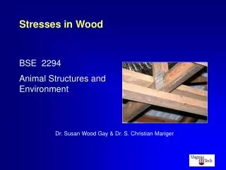
Boundary Conditions (0) (0) (-1) (1) (2) (-1) (1) (2) (3) o o o o o o o o o x x 4-Point Formulae 5-Point Formulae
Boundary Conditions: 4-Point Formulae 1st order derivative x = [ -1/3 (-1) - 1/2 (0) + (1) - 1/6 (2)] /x which gives (-1)= [ -3/2 (0) + 3 (1) - 1/2 (2) - 3x x (0) Similarly, 2nd order derivative (-1)= [ 2 (0) - (1) + 3 2x xx (0) Fixed or Built-in Edge : at x = a , then (a) = 0 and x (a) = 0 (-1)= 3 (1) - 1/2 (2) Simply-Supported Edge : at x = a , then x (a) = 0 and Mx = 0 xx (a) = 0 (-1)= (1)
Initialization INIT READIN Read Input Data SUMMAR Print Input Summary Setup [ Z ] and [ Q ] matrices ZQMAT Solve for U and simultaneously SOLVE Print deflection w andstress at each mesh point OUTPUT PROGRAM LAMINA
Si3N4 SiO2 Silicon <100>Substrate Thin Diaphragm Typical multi-layer Diaphragm
Silicon <100>Substrate Thin Diaphragm A Silicon Diaphragm
SiO2 Silicon <100>Substrate Silicon-dioxide Diaphragm
Si3N4 SiO2 Silicon <100>Substrate Thin Diaphragm A multi-layer Diaphragm bent concave by point or distributed loads Point or distributed load
Si3N4 Compressive stress due to cooling SiO2 Silicon <100>Substrate Thin Diaphragm A multi-layer Diaphragm bent convex by temperature stresses
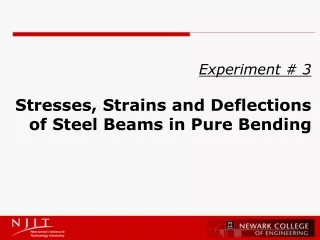
Deflection at center ‘’ for lateral loads ‘q’ Table 1 Deflection at center `w ' for lateral loads `q' (Reference for known results is Timoshenko [1]) ------------------------------------------------------------------ | serial | Boundary conditions | known results | LAMINA | | no. | | | simulation | ------------------------------------------------------------------ | 1 | X-edges fixed | 0.260E-2 | 0.261E-2 | | | Y-edges free | (TIM pp 202) | | | | | | | | 2 | X-edges simply supp.| 0.130E-1 | 0.130E-1 | | | Y-edges free | (TIM pp 120) | | | | | | | | 3 | All edges fixed | 0.126E-2 | 0.126E-2 | | | | (TIM pp 202) | | | | | | | | 4 | All edges simply | 0.406E-2 | 0.406E-2 | | | supported | (TIM pp 120) | | ------------------------------------------------------------------
Deflection at center for lateral and in-plane loads P Table 2 Deflection at center for lateral and in-plane loads (Reference is Timoshenko [1], pp 381) ------------------------------------------------------------- |serial | Normalized | known results | LAMINA | | no. | in-plane load | | simulation | ------------------------------------------------------------- | 1 | Tensile NX=NY=NO=1 | 0.386E-2 | 0.384E-2 | | | | | | | 2 | Tensile NO = 19 | 0.203E-2 | 0.202E-2 | | | | | | | 3 | Compressive NO=-1 | 0.427E-2 | 0.426E-2 | | | | | | | 4 | Compressive NO=-10 | 0.822E-2 | 0.830E-2 | | | | | | | 5 | Compressive NO=-20 | (indefinite) | (-0.246E+0)| -------------------------------------------------------------
Deflection at center for uniform bending moment Table 3 Deflection at center for uniform bending moment (Reference is Timoshenko [1], pp 183) ------------------------------------------------------------- | serial | condition | known results | LAMINA | | no. | | | simulation | ------------------------------------------------------------- | 1 | MO = 1 | 0.736E-1 | 0.732E-1 | | | on all edges | | | ------------------------------------------------------------- M M
Diaphragm consisting of Si, SiO2 and Si3N4 layers Table 4 Diaphragm consisting of Si, SiO2 and Si3N4 layers ------------------------------------------------------------- |serial| lamina | Deflection |In-plane | stress | | no. | layers | at center |resultant | couple | ------------------------------------------------------------- | (a) | SiO2+ Si+ SiO2 | 0 | -0.216E+2 | 0 | | | | | | | | (b) | Si + SiO2 | -0.583E-2 | -0.381E+1 | -0.628E-1 | | | | | | | | (c) | SiO2+ Si | +0.583E-2 | -0.381E+1 | +0.628E-1 | | | | | | | | (d) | Si+SiO2+ Si 3N4 | +0.583E-3 | +0.191E+2 | +0.168E-1 | | | | | | | | (e) | SiO2+ Si+ SiO2 | +0.515E-2 | +0.643E+0 | +0.727E-1 | | | + Si 3N4 | | | | -------------------------------------------------------------
Conclusions • LAMINA takes into account • Single Crystal anisotropy in elastic constants • Temperature effects – growth and ambient • Heteroepitaxy, lattice constant mismatch induced strains • LAMINA accepts • Square or rectangular diaphragm/beam/cantilever • non-uniform grid spacing in x- and y-directions • non-uniform thickness at each grid point – taper • LAMINA can be used as design tool • to minimize deflections (at the center) • minimize in-plane stresses in Si, SiO2 and Si3N4 • make the diaphragm insensitive to temperature or packaging parameters
Thank You Web-pagehttp://www.tifr.res.in/~apte/LAMINA.htm
4 3 11 5 10 6 2 1 12 9 7 13 8 slide5 1 -2 1 -4 1 1 -4 6 1 -2 1 -2 -2 4 1 1 -2 13 - point Formulationof Finite Differencesfor 4th order derivatives