Download
1 / 55
550 likes | 869 Views
Electrical Activity of the Heart. Introduction. Where does the “electro” in electrocardiography come from?. Under this condition, the heart cell is said to be polarized. Polarization. Imagine two micro-electrodes; one outside the cell, one inside the cell

E N D
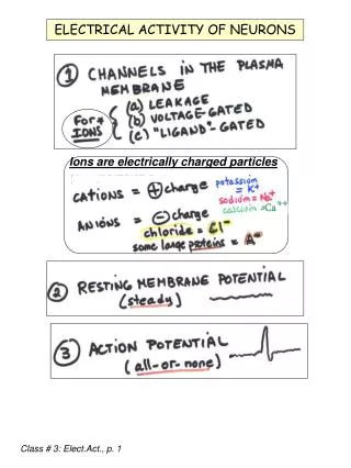
Introduction • Where does the “electro” in electrocardiography come from?
Under this condition, the heart cell is said to be polarized
Polarization • Imagine two micro-electrodes; one outside the cell, one inside the cell • Difference between the two equals -90 mV inside • The cell is said to be ‘polarized’
Action Potential Depolarization Repolarization
closedgates opened gates Action Potential in Skeletal Muscle Fiber
Action Potential Skeletal Cardiac
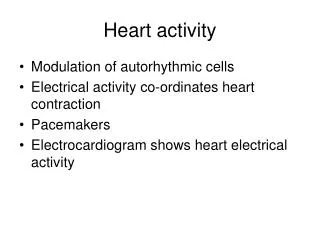
Myocyte Action Potentials • Fast and Slow • Fast = non-pacemaker cells • Slow = pacemaker cells (SA and AV node)
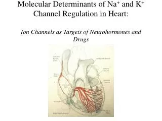
Action Potential • Ion influx • Na channels (fast and slow) • K channels • Ca channels
Inside Outside thevirtualheart.org/CAPindex.html
Action Potential • Phase 0 • Stimulation of the myocardial cell • Influx of sodium • The cell becomes depolarize • Inside the cell = +20 mV
Action Potential • Phase 1 • Ions • Influx of sodium • Efflux of potassium • Partial repolarization • Phase 2 • Ions • Sodium • Efflux of potassium • Influx of calcium • Plateau
Action Potential • Phase 3 • Ions • Efflux of potassium* • Influx of calcium • Repolarization (slower process than depolarization) • Phase 4 • Interval between repolarization to the next action potential • Pumps restore ionic concentrations
Refractory Periods • Absolute refractory period - phase 1 - midway through phase 3 • Relative refractory period - midway through phase 3 - end of phase 3
SA Node Action Potential • “Funny” currents (phase 4); slow Na channels that initiate spontaneous depolarization • No fast sodium channels • Calcium channels (slow) • Long-lasting, L-type • Transient, T-type • Potassium channels
Action Potentials • Fast and Slow
Action Potentials It is important to note that non-pacemaker action potentials can change into pacemaker cells under certain conditions. For example, if a cell becomes hypoxic, the membrane depolarizes, which closes fast Na+ channels. At a membrane potential of about –50 mV, all the fast Na+ channels are inactivated. When this occurs, action potentials can still be elicited; however, the inward current are carried by Ca++ (slow inward channels) exclusively. These action potentials resemble those found in pacemaker cells located in the SA node,and can sometimes display spontaneous depolarization and automaticity. This mechanism may serve as the electrophysiological mechanism behind certain types of ectopic beats and arrhythmias, particularly in ischemic heart disease and following myocardial infarction.
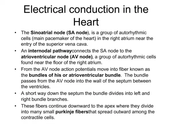
Conduction speed varies throughout the heart • Slow - AV node • Fast - Purkinje fibers
Action Potential • ECG records depolarization and repolarization • Atrial depolarization • Ventricular depolarization • Atrial repolarization • Ventricular repolarization
The Body as a Conductor This is a graphical representation of the geometry and electrical current flow in a model of the human thorax. The model was created from MRI images taken of an actual patient. Shown are segments of the body surface, the heart, and lungs. The colored loops represent the flow of electric current through the thorax for a single instant of time, computed from voltages recorded from the surface of the heart during open chest surgery.
Assignment • Read “Non-pacemaker Action Potentials” • Read “SA node action potentials”
Basic ECG Waves • Chapter 2
ECG Paper • Small boxes = 1 mm • Large boxes = 5 mm • Small boxes = 0.04 seconds • Large boxes = 0.20 seconds • 5 large boxes = 1.0 second • Paper speed = 25 mm / sec
ECG Paper • Horizontal measurements in seconds • Example, PR interval = .14 seconds (3.5 small boxes)
ECG Paper • Standardization mark • 10 mm vertical deflection = 1 mVolt
ECG Paper • Standardization marks • Double if ECG is too small • Half is ECG is too large Top: Low amplitude complexes in an obese women with hypothyroidism Bottom: High amplitude complexes in a hypertensive man
ECG Description • ECG amplitude (voltage) • recorded in mm • positive or negative or biphasic
ECG Waves • Upward wave is described as positive • Downward wave is described as negative • A flat wave is said to be isoelectric • Isoelectric as describes the baseline • A deflection that is partially positive and negative is referred to as biphasic
ECG Waves • P wave • atrial depolarization • ≤ 2.5 mm in amplitude • < 0.12 sec in width • PR interval (0.12 - 0.20 sec.) • time of stimulus through atria and AV node • e.g. prolonged interval = first-degree heart block
ECG Waves • QRS wave • Ventricle depolarization • Q wave: when initial deflection is negative • R wave: first positive deflection • S wave: negative deflection after the R wave
ECG Waves • QRS • May contain R wave only • May contain QS wave only • Small waves indicated with small letters (q, r, s) • Repeated waves are indicated as ‘prime’
ECG Waves • QRS • width usually 0.10 second or less
ECG Waves • RR interval • interval between two consecutive QRS complexes
ECG Waves • J point • end of QRS wave and... • ...beginning of ST segment • ST segment • beginning of ventricular repolarization • normally isoelectric (flat) • changes-elevation or depression-may indicate a pathological condition
ECG Waves • T wave • part of ventricular repolarization • asymmetrical shape • usually not measured
ECG Waves • QT interval • from beginning of QRS to the end of the T wave • ventricular depolarization & repolarization • length varies with heart rate (table 2.1) • long QT intervals occur with ischemia, infarction, and hemorrhage • short QT intervals occur with certain medications and hypercalcemia
ECG Waves • QT interval should be less than half the R-R interval • If not, use Rate Corrected QT Interval • normal ≤ 0.44 sec.
ECG Waves FYI • Long QT interval • certain drugs • electrolyte distrubances • hypothermia • ischemia • infarction • subarachnoid hemorrhage • Short QT interval • drugs or hypercalcemia
ECG Waves • U Wave • last phase of repolarization • small wave after the T wave • not always seen • significance is not known • prominent U waves are seen with hypokalemia
Heart Rate Calculation • For regular rhythm... • Count the number of large boxes between two consecutive QRS complexes. Divide 300 by that number • 300 ÷ 4 = 75 • Count the small boxes. Divide 1500 by that number • 1500 ÷ 20 = 75