Download
1 / 52
670 likes | 1.32k Views
Workshop on Silicon Photonics Mainz, November 10 2006. Silicon-on-Insulator based Nanophotonics Why, How, What for?. Roel Baets Ghent University - IMEC

E N D
Workshop on Silicon Photonics Mainz, November 10 2006 Silicon-on-Insulator based NanophotonicsWhy, How, What for? Roel Baets Ghent University - IMEC Wim Bogaerts, Pieter Dumon, Dirk Taillaert, Dries Van Thourhout, Shankar Kumar Selvaraja, Gunther Roelkens, Joris Van Campenhout, Joost Brouckaert
Overview • Introduction to SOI nanophotonics • Why? • What for? • How? • Conclusions
The key bottleneck of photonic integration • (By far too) many degrees of freedom • many different materials • many different component types • many different wavelength ranges • Hence: • no generic integration technology for many different applications • no high volume technology platforms • too high cost • Hence: Integration is not an industrial reality (yet)
The way out - a roadmap • 1. Use mainstream Silicon(-based) technology • wherever possible, CMOS fab compatible • otherwise, use dedicated Silicon fab • 2. Add other materials where needed • for specialty functions • if the added value motivates it • 3. By using • wherever possible : wafer-scale front-end and back-end technology • otherwise, die-scale technology • 4. Build a photonic IC industry on this basis
Nanophotonics High index contrast: photonic crystals, photonic wires Strong confinement: small waveguide cores, sharp bends Silicon-on-insulator Transparent at telecom wavelengths (1550, 1300nm) High refractive index contrast 3.45 (Silicon) to 1.0 (air) SOI nanophotonic waveguides • Both cases: • feature size : 50-500 nm • required accuracy of features: 1-10 nm • NANO-PHOTONIC waveguides
SOI-nanophotonic wires And many others …
Why? • 3 sets of good reasons: • Functionality + performance • Technology • Cost • Or why not? • The polarisation problem • The extreme accuracy problem • The source problem
Increasing Index Contrast Low Contrast - Fiber Matched (silica or polymer based) Bend Radius ~ 5 mm Size ~ several cm^2 5 cm 5 mm 200 mm Medium Contrast (InP-InGaAsP) Bend Radius ~ 500mm Ulra-high Contrast (SOI based) Bend Radius < 5mm
0.08 0.06 Excess bend loss [dB/90°] 0.04 0.02 0 1 2 3 4 5 Bend radius [µm] Bend losses • Increase for narrower waveguides: • Weaker confinement: bend radiation • More sensitive to roughness • Increase for smaller bend radii • e.g. wire width = 540nm 0.09dB/90° 0.027dB/90° 0.01dB/90° 0.004dB/90°
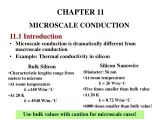
Technology • Need: • smallest feature size : 50-500 nm • required accuracy of features: 1-10 nm • required aspect ratios: mostly < 1:1 • This matches amazingly well with the capabilities of advanced CMOS
248nm excimer laser Lithography ASML PAS 5500/750 Step-and-scan Automated in-line processing (spin-coating, pre- and post-bake, development) 4X reticles Standard process 193nm excimer laser Lithography ASML PAS 5500/1100 Step-and-scan 4X reticles Fabrication with deep UV Litho
Low cost • Wafer-scale fabrication on large wafers with high yield • Wafer-scale testing • Low cost packaging
1mm Coupling into SOI nanophotonics • Important: • Low loss • Large bandwidth • Coupling tolerance • Fabrication • Limited extra processing • Tolerant to fabrication • Polarization SOI wire Single-mode fiber
0.4mm 0.2mm 80nm polished facet 500 mm Coupling to fiber – Inverse taper • Inverse taper • Broad wavelength range • Single mode • Easy to fabricate (if you can do the tips) • Low facet reflections
single-mode fiber core 1-D grating taper Vertical Fibre Coupler • 1-D grating • Butt-coupled • Period ~ 600 nm • 20 periods • Etch depth = 45 nm • Simple design: 31% coupling • Bandwidth: ~ 50nm air air air air Si SiO2 Si Taillaert et al, JQE 38(7), p. 949 (2002)
Z X Alignment tolerances • good alignment tolerances • measurement of P/Pmax versus fiber position Taillaert et al, JQE 38(7), p. 949 (2002)
The polarisation problem • High index contrast makes polarisation independence (almost) impossible.
Single mode fiber core 2D grating fiber coupler – polarisation splitter • Fiber to waveguide interface for polarisation independent photonic integrated circuit • 2D grating • couples each fiber polarisation in its own waveguide • in the waveguides the polarisation is the same (TE) • Allows for polarisation diversity approach
Polarisation Diversity Circuit single-mode fiber light in light out 2-D grating TE-polarization TE-polarization split polarisations identical circuits combine polarisations z y 2-D grating x
Experimental results • Fabrication • SOI: 220nm Si / 1000nm SiO2 • Etch depth: 90nm • Square lattice of holes: 580nm period
The extreme accuracy problem • High index contrast components: • - interference based filters, • with d the waveguide width () • - cavity resonance wavelength • with d the cavity length (a few ) • - photonic crystal • with d the hole diameter () if tolerable wavelength error : 1 nm tolerable length scale error : (of the order of) 1 nm
The source problem • How to integrate sources: • that are compact • that are efficient • that have high modulation bandwidth • by means of wafer-scale processes • ?????????????????????????????????????? • Approaches: gain from • optical pumping • Raman gain • Four wave mixing gain • Nanocrystals • electrical pumping • nanocrystals? • Impurity doped Silicon? • bonded III-V layers : most successful approach to date
Applications • Transceivers • WDM components • Intra-chip optical interconnect • Sensors • Digital photonics • …
Optical Ring Resonators • Ring resonator demux • 4 rings in series • Linearly increasing radius • lc does not increase linearly as expected !! • Fabrication problem: mask discretisation
0 FSR=25.3nm -10 1 2 3 4 8 16 1 Normalized tansmission [dB] -20 -30 1.52 1.56 1.53 1.54 1.55 wavelength [µm] Arrayed Waveguide Grating • 16-channel AWG, 200GHz • 200µm x 500µm area • -3dB insertion loss • -15dB to -20dB crosstalk 100µm
P2 P2 P1 P1 Polarization diversity duplexer downstream upstream • Duplexer for WDM-PON access network • Polarization diversity approach • 2-D fiber couplers: polarization splitting • AWG: • 2 x 400GHz bands • bidirectional propagation 400GHz 50GHz 150GHz wavelength P2 P1 P1 P2 P1 AWG P1 P2 P2 P1 downstream band upstream band input grating
Polarization diversity duplexer • Results: • Crosstalk: -15dB • Insertion loss: -2.2 to -5.6dB • Nonuniformity (intra-band): 3.4dB • Polarization dependent loss: 0.66dB 100µm ref in out 1a 1b 2a 2b ref
Mach-Zehnder Lattice Filter • Channel drop, 1 out of 8 • Δfch = 200GHz • 11th order filter • -15dB crosstalk
1 μm Planar Concave Gratings • Diffraction grating in slab waveguide deeply etched teeth free propagation region shallow-etch apertures 500 nm wide photonic wires 50 μm
Results • Channel spacing: 20nm • Insertion loss: 7.5dB • Channel uniformity: 0.6dB • Crosstalk: better than -30dB • Footprint: 250 x 150 μm2
To detectors InGaAs Detectors on SOI Measured response of 4 detectors
100 10 1 Fréquency (GHz) 0,1 0,01 1998 2000 2002 2003 2005 Year Ge Photodetectors Ti/AlCu/TiN/Ti • Germanium on Silicon • p-i-n photodiode • coupled to waveguide • Could be monolithicallyintegrated on/on SiliconPlotted: Speed evolution in recent years Ti/TiN/W Implanted Ge • Colace, Massini & al., Univ. Rome Oh & al.,Univ.Texas Dehlinger & al., Infineon and IBM Jutzi & al., Univ. Stuttgart Dosonmu & al., Univ. Boston and MIT CEA-LETI & IEF Si waveguide
Ring modulator • Ring resonator in p-i-n junction • Carrier injection • Change refractive index • Change resonance 10GHz operation signal ground ground waveguide in p-i-n
Strained Silicon • Silicon: • centrosymmetric crystal structure • no electro-optic effect • Apply Si3N4 strain layer • Deform crystal structure • Induce electro-optic effect: χ(2) ~15pm V-1 Jacobson et al., nature 04706 (May 2006)
“Hybrid Silicon Laser” • AlGaInAs membrane bonded on SOI wafer • length ~800µm • Cavity defined only by silicon waveguide (no critical alignment) Fang et al. OpEx 14(20), p. 9203 (2006)
2% NaCl 2,05% NaCl 2,15% NaCl 4% NaCl SOI microring sensor • Measure salt concentration • Fluid overcladding • Refr. index ~ Salt concentration • Response of ring ~ refr. index • Q = 20000 minimum n ~ 5.10-5
SOI NEMS Vibration Sensor • SOI directional coupler • 2 waveguides close together: light leaks • coupling efficiency ~ waveguide spacing • Freely Suspended directional coupler • Oxide removal • Vibrations change spacing Iwijn de Vlaminck, IMEC
Photonic Crystals • NTT • E-beam lithography • Low propagation losses: 6dB/cm • Low-loss interface to fiber • IBM • In-house CMOS processes • e-beam lithography is theonly out-of-the-line step • Photonic crystals: low propagation losses • Slow light in Photoniccrystals (Nature, 3/11)
Integration with CMOS • Luxtera • Fabless Silicon Photonics (Fabrication by Freescale) • Integration of CMOS and photonic circuits:Waveguides are defined together with transistor gates • Low-loss rib waveguide • Grating fiber couplers
Silicon Optical Filters - DWDM electrically tunable integrated w/ control circuitry enables >100Gb in single mode fiber Silicon 10G Modulators driven with on-chip circuitry highest quality signal low loss, low power consumption Flip-chip bonded lasers wavelength 1550nm passive alignment non-modulated = low cost/reliable Complete 10G Receive Path Ge photodetectors trans-impedance amplifiers output driver circuitry • The Toolkit is Complete • 10Gb modulators and receivers • Integration with CMOS electronics • Cost effective, reliable light source • Standard packaging technology Fiber cable plugs here Ceramic Package Luxtera CMOS Photonics
Cost of ownership • Cost of ownership of advanced CMOS technology is too high for: • most research entities in Silicon photonics • most photonic component companies • Hence the need for a • fabless model
THE challenge of Silicon photonics • CMOS • large, mature technology base • strong, focused innovative drive • large organisations, big budgets • Silicon Photonics • Recent rapid progress • (still) relatively small actors • limited budgets • Successful industrial deployment requires extensive interaction between CMOS and photonics community Challenge:overcome this mismatchwith a critical mass
Silicon Photonics Platform • Network of Excellence ePIXnet develops platforms for photonic integration: • Silicon photonics platform • InP photonics platform • Nanostructuring platform • Packaging platform • High speed measurement platform • Modelling platform www.epixnet.org
Si Photonics platform • Long-term objective: • to enable a route towards commercial deployment of silicon photonics. • Methodology: • Facility Access Programme (foundry service)for Research and Prototyping: • Making mature fabrication processes on high-end industrial CMOS tools available to many research groups or projects • Sharing masks and processing: dramatic cost reduction • Roadmap for Silicon Photonics Technologies: • Identifying the challenges and evolutionary solutions in this field • Commercial Manufacturing Routes: • Gradual involvement of commercial foundries • Promotion and lobbying • For the field of Silicon photonics in the interest of Europe’s position in this field.
Platform structure • Steering group: strategic decisions • Coordinator : daily operation • Core fabrication partners • IMEC (Gent-Leuven) • CEA-LETI (Grenoble) • Other in the future? • Members • Anybody interested in and committed to the mission • Users • Those who use the foundry service