BASIC ELECTRICITY
BASIC ELECTRICITY. VOLTAGE AMPERAGE OHMS. Page 242. Autobody Text. SERIES CIRCUIT RULES. The current through each resistance is the same. The sum of individual voltage drops is equal to the source voltage The total circuit resistance is equal to the sum of the individual resistance's.

BASIC ELECTRICITY
E N D
Presentation Transcript
BASIC ELECTRICITY • VOLTAGE • AMPERAGE • OHMS Page 242 Autobody Text
SERIES CIRCUIT RULES • The current through each resistance is the same. • The sum of individual voltage drops is equal to the source voltage • The total circuit resistance is equal to the sum of the individual resistance's Chap 1 Handout - Page 9
PARALLEL CIRCUIT RULES • The sum of the branch circuit currents is equal to the total circuit current • The voltage drop across each branch circuit is the same • The current in each branch circuit is different if the resistance values are different. Chap 1 Handout - Page 10
PARALLEL CIRCUIT RULES CONT’D • The total circuit resistance (equivalent resistance) is less than the value of the lowest resistance. • The equivalent resistance for two resistance's in parallel is equal to the product divided by the sum Chap 1 Handout - Page 10
Ohm’s Law V V = AxR V = IxR V = IxO All the same A x R Chap 1 Handout - Page 8
COMMON CIRCUIT FAILURES • OPEN CIRCUIT • GROUNDED CIRCUIT • SHORT CIRCUIT • POOR CONNECTIONS Autobody Text - Page 242
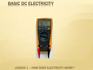
DIGITAL VOLT-OHMMETER • 10 MEG OHM IMPEDANCE • DIGITAL READOUT VERY PRECISE • MULTI-METER (MULTI-USES) • DIODE TESTER • AUDIBLE CONTINUITY TESTER • OVERRANGE INDICATOR Autobody Text - Page 243
DVOM VOLTAGE TESTS • Power Switch • Polarity • Start with highest range and turn down range until most accurate reading • Over-range indicator • Low battery • Hook across (parallel) device or circuit being tested Autobody Text - Page 244
DVOM AMPERAGE TESTS • Fuse Protection • Hook in series with circuit • Function selector adjust to most accurate range • Maximum amperage of meter
DVOM OHMMETER TESTS • Isolate component to be tested • fuse protected • Function selector to most accurate range Autobody Text - Page 244
Reading the DVOM Handout
TEST LIGHTS • NON POWERED LIGHT • TELLS PRESENCE OF VOLTAGE • EASY AND QUICK TO USE • LOW INTERNAL IMPEDANCE • SELF POWERED LIGHT (CONTINUITY TESTER) • WORKS LIKE OHMMETER • LOW COST Autobody Text - Page 245
LOGIC PROBE • TELLS PRESENCE OF VOLTAGE • TELLS PRESENCE OF GROUND (LOW VOLTAGE) • WILL NOT HURT COMPUTER CIRCUITS • LIGHT AND AUDIBLE TYPE
JUMPER WIRES • USED FOR TEST PURPOSES • ABOUT 6”, 12” 3 FT, AND 15 FT. • LARGE ENOUGH GAUGE • DIFFERENT TERMINAL ENDS • ALLIGATOR CLIPS