Download
1 / 16
180 likes | 503 Views
Nanostructured carbon Electrospinning . S.M. Bennington ISIS. Horizon Scanning Meeting 9 th September 2008. Electrospinning. The People Involved Arthur Lovell - STFC Zeynep Kurban – STFC/UCL Derek Jenkins - STFC Bob Stevens - STFC. Electrospinning.

E N D
Nanostructured carbonElectrospinning S.M. Bennington ISIS Horizon Scanning Meeting 9th September 2008
Electrospinning The People Involved • Arthur Lovell - STFC • Zeynep Kurban – STFC/UCL • Derek Jenkins - STFC • Bob Stevens - STFC
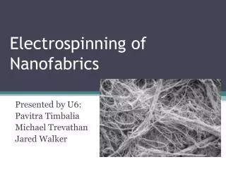
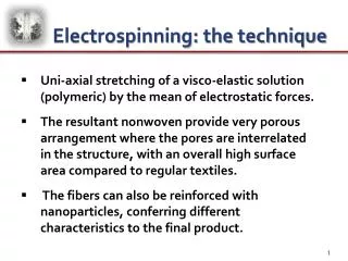
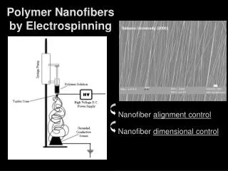
Electrospinning • A droplet of polymer in solution is created with a syringe pump • High voltage is used to pull a fibre from the droplet • The solution evaporates before the fibre hits the collection plate This is a highly controllable process able to produce fibres from 10 µm to 10’s of nm
polymer solution: type of polymer polymer concentration molecular weight viscosity conductivity-dielectric constant, surface tension Physical variables flow rate electric potential distance between the capillary and collection screen Variables
Solutions • PAN in DMSO (4.2-10 wt%) MW = 150,000 • PAN in DMF (8-10 wt%) • PANI in DMSO (5 wt%) Mw = 50, 100 and 300,000 • PAN+PANI in DMSO (9.5+0.5, 9+1,3.6+0.6 wt%) • PAN in HFIP (0.25, 0.37, 0.5, 0.67, 0.75 wt%) • Other controls • Controlled the surface tension with surfactant (SASH) • Controlled the conductivity with salts
To minimise diameter: Low viscosity (without beading) Low flow rate (200 µl/hr used) Low surface tension (add surfactant) High conductivity (add ions and surfactant) Low voltage Increased distance between plate and capillary (27cm) Fibre Diameters
Production carbon fibres • The variables are: • Time • Temperature • Stress • Impurity content
Fibre formation 1500ºC 2500ºC Oxygen stabilized No oxygen stabilization
1500ºC 2200ºC 2500ºC 2800ºC
TEM CNF Graphitisated at 2800ºC
Co-axial fibres Can encapsulate liquids or solids inside polymer
Summary • Able to create Polymer fibres 50 to 1µm in diameter and 100,000km long • Can graphitize these to make CNF of varying crystallinity • Now working on coaxial fibres
Schematic decomposition of PAN during pyrolysis Heat PAN polymer chain 400-600°C Dehydrogenation 600 -1300°C Denitrogenation