Download
1 / 25
250 likes | 266 Views
Detailed progress report on beam line studies, detection systems, magnet prototypes, and ongoing experiments for the mgeg collaboration. Includes results, comparison, challenges, and future plans.

E N D
Report on the Progress formgeg ExperimentSatoshi MiharaICEPP, Univ. of Tokyofor the mgeg collaboration Beam Line Studies Superconducting Solenoidal Magnet Photon Detector Timing Counter Drift Chamber Trigger Electronics HV and Slow Control System
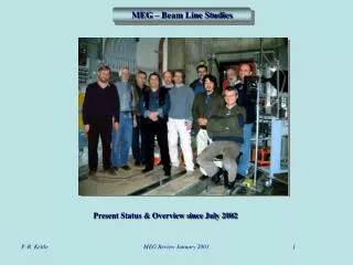
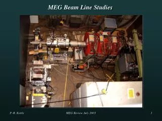
Beam Line Studies • 2 separate branches of the beamline • U-branch (present) • Z-branch (previous) • The present results are based on a comparative study on the U-branch with the aim of: • Measuring the phase space parameters • Improve the separation quality of muons over positrons by using a spectrometer + degrader as a cleaning stage • Degrading was done in a field-free region (Mylar: more radiation resistant than CH2) • 2mmt CH2-collimator with either a 50 or 80mmd hole • Beam test performed in Sep-Oct ’01, but was ended by a technical problem in the primary beam-blocker system of the beam line.
Beam Line StudiesMeasurement Techniques • Pill counter on a X-Y scanner table • Stopping target of 1mmt CH2-plate with trigger telescope counters S1,S2 and MWPC1/2, and a large NaI counter • Profile MWPC system to measure the beam profile anddivergences Digital oscillo output from a pill counter e m
1/2.1 1/5.5 m beam spectrometer degrader Beam Line Studies Results • Intensities* and Phase Space • w/o degrader: 3.5 ·108 m+s-1could be transported to the spectrometer • Loss factor 2.1 in the spectrometer and 5.5 between the degrader and the entrance to the area • Spot size:23mm horizontally 68mm vertically (FWHM) at the final focus with a Mylar degrader • The increased vertical divergence in the degrader affects the loss. Further investigation is required… • Separation Quality • At the peak, 16.5 times suppression • There is a large decay positron BG. Further investigation is required… High beam momenta *quoted values were obtained using the pill-counter method
U/Z-Branch Comparison • In the U-branch positron contamination seems to be more than 2.5 times higher • Positron suppression factor is clearly better in the U-branch • More than a factor of 6 difference in Nm at the final focus • Factor of 5.5 loss of muons • Large decay positron BG • g a few possibilities are considered to solve the problem • 8 weeks beam time is planned in 2002 (4w in July and 4w in Oct)
SuperconductingSolenoidal Magnet • To minimize the magnetic field strength in the photon detector region. • Radii of the magnet were shrunk by 10% • Compensation coils (normal conductor) • No additional material in the central region.
Superconducting Cable • High-strength Al stabilized superconducting cable • Delivered! (L=18km) • Cable performance measured • OK! (mm)
Comparison withthe Proposal Design • No significant difference in the features such as constant bending radius even with compensation coils With compensation coils Proposal
Photon DetectorLarge Prototype • sE, st, and sx • Total system check in a realistic operating condition: • Monitoring/controlling systems • Sensors, liquid N2 flow control, refrigerator operation, etc. • Components such as • Feedthrough,support structure for the PMTs, HV/signal connectors etc. • PMT long term operation at low temperature • We have been examining • Performance of the refrigerator and other detector components • Abs. Length in LXe by means of cosmic rays. • Detector performance using gamma beam
Photon DetectorCryogenics and Refrigerator R&D • Total heat load 52W in the LP vessel • 18W from PMTs, • 10W from cables • 24W static (as small as design value) • Successful operation of the pulse-tube refrigerator (70W) in LP for more than 50 days • R&D to upgrade the cooling power of the refrigerator is in progress • From a Co-axial to a U-shape to increase the cooling power to above 250W • Planning to employ two 250W refrigerator in the final detector
PMT Thin Al window LXe g Honeycomb filler Photon DetectorDetector Components • Most of detector components – feedthrough connectors, sensors to monitor temp., pressure and surface level of LXe , PMT support structure – worked reasonably well. • However silicon rubber filler posed some problems. After a few cooling tests, some PMTs with the filler seemed to receive tiny CRACKS holder New filler material: Epoxy(STYCAST) + glass beads (0.5mm diameter)
Photon DetectorCosmic & Gamma beam tests • Studies with cosmic rays • Examine the detector response and stability under the real conditions • Evaluate labs (cf. dedicated experiment in preparation ) • Studies with gamma beam • Performed in May at TERAS • Two major problems • PMT filler some PMTs on the front wall inoperative. • Hardware problem… could not fixed during the scheduled beam time Very Preliminary
Photon DetectorFinal Detector Design • MC • Two independent simulation codes are being compared • Position measurements are less dependent on the labs. • Energy measurement is more sensitive. • Results will be summarized in a separate report. • Calibration • PMT gain and QE monitored using LEDs and alpha sources Installation to the vessel 2D movable alpha source or Line-type source PMT test and calibration at 165K using the LP vessel E, position: Using g from p0s timing: radiative muon decays
Photon DetectorVessel Design • Cryogenic design work of the vessel started based on the experiences obtained with the large prototype. • R&D work on the inner front window has also been started.
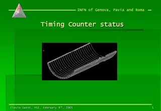
Timing CounterPrototype R&D at CORTES Facility • The COsmic Ray TESt (CORTES) facility • Prototype test • Preliminary measurement on a 1cm thickness prototype (BC404, wrapped with 50mm of Al Mylar), with Philips XP2020 UR and Hamamatsu R5946
Timing CounterResults and future prospect • Results Promising results (s = 60 ps)! Resolution dominated by photoelectron statistics, and depends on the square root of the Npe • MC simulations 40 ps timing resolution g lower cut of 5MeV energy deposit g0.5cm inner layer and 2cm outer layer to achieve 94% detection efficiency • Engineering Design has been Started
Drift Chambermini prototype • Study engineering problems involved in the construction • Measure signal characteristics for optimal design of front-end electronics • Measure drift properties at • 0,0.6, 0.6, 1T field • 3 tilting angles
Drift Chamber Prospect • 1st Prototype has shown that the main mechanical problem can be solved. • 2nd set of test chamber modules for studying: • Cathode readout • Replace the common middle cathode by two separated cathodes. • Charge division • Study of the impedance of the anode wires to better mach the readout prints and pre-amps. • Gas amplification Common middle cathode
g e + Trigger Electronics I • MC simulation predicts: • Beam rate 108 s-1 • Fast LXe energy sum > 45MeV 2103 s-1 • g interaction point • e+ hit point in timing counter • time correlationg – e+ 200 s-1 • angular correlationg – e+ 20 s-1 • FPGAs coupled with 100MHz FADC are able to implement the algorithms.
Trigger Electronics II • Type1(VME6U) • Receives and digitizes the PMT signals • Transmit digitized info to Type 2 board • Type2(VME9U) • Completes the triggering algorithms. • For synchronous operation 100MHz clock is distributed. • Total trigger latency 350ns • Present Status • Components both for Type 1 and Type 2 were already purchased. • Type 1: design work completed and simulation work is going on. Type 1 Type 2
HV and Slow Control System • New slow control system • RS485 network with dedicated nodes • Microcontrollers with both AD and DA converters • Prototype tested at PSI Drift Chamber test facility. • New high voltage power supply • Same scheme with the slow control system • Cheaper by a factor of 4 compared to commercial ones • Stability and accuracy of +/-0.3V • See details at http://midas.psi.ch/mscb
Sensitivity Accidental background rate Single event sensitivity
Summary • Beam line studies: • Test performed in Sep-Oct ’01, m/e separation using a cleaning stage • Further investigation is required to understand the beam line. • Beam test is planned in Jul and Oct ’02 • Superconducting solenoidal magnet • Compensation coil to reduce the magnetic field strength in the photon detector region • Coil winding started • Photon detector • R&D works using LP still continues • Gamma beam test is planed at the beginning of this year • Positron timing counter • Prototype tested at CORTES facility • Engineering design has been started • Drift chamber • 1st prototype successful • 2nd sets of prototype coming soon • Trigger electronics • Two kinks of trigger boards on which FPGAs and FADC are equipped. • Slow control and HV • New slow control and HV system using microcontroller