Download
1 / 19
190 likes | 337 Views
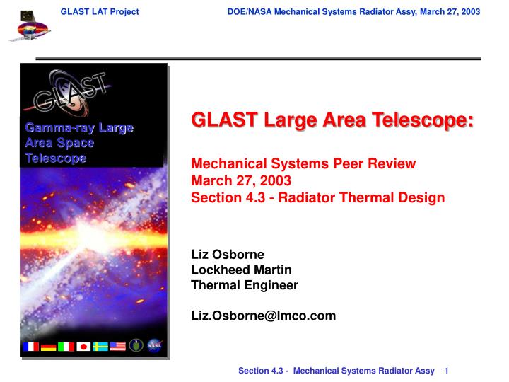
Gamma-ray Large Area Space Telescope. GLAST Large Area Telescope: Mechanical Systems Peer Review March 27, 2003 Section 4.3 - Radiator Thermal Design Liz Osborne Lockheed Martin Thermal Engineer Liz.Osborne@lmco.com. Topics. Requirements Thermal Design Overview

E N D
Gamma-ray Large Area Space Telescope GLAST Large Area Telescope: Mechanical Systems Peer Review March 27, 2003 Section 4.3 - Radiator Thermal Design Liz Osborne Lockheed Martin Thermal Engineer Liz.Osborne@lmco.com
Topics • Requirements • Thermal Design Overview • Thermal Design Environments • Orbital Environment • Spacecraft Interface • Thermal Control • Variable Conductance Heatpipes • Thermal Surfaces • Heaters • Thermal Model • Results • Hot Operation, Cold Operation, Survival • Summary & Future Work
Driving Thermal Requirements Based on: Radiator Level IV Design Specification, LAT-SS-00394-1-D6, Draft, Dated 5 Mar 2003 LAT Mechanical Systems Interface Definition Dwg, Radiator-LAT Interface, LAT-DS-01221, Draft, Dated 25 Feb 2003
Thermal Design Overview • Radiators • Two panels, parallel to the LAT XZ-plane • Size per panel: 1.82 m x 1.56 m = 2.8 m2 • Construction • Aluminum honeycomb structure • 6 Variable-Conductance Heat pipes (VCHP’s) on each Radiator panel • Interface to XLAT CCHP’s and LAT DSHP’s at each Radiator Interface Temperature (RIT) • Provide active feedback control of grid temperature through VCHP’s RIT (6 places)
Thermal Design Environments Cold Orientation Hot Orientation Survival Orientation
Interface to Spacecraft & LAT • Solar Arrays strong influence on Radiators • Hot design: Arrays begin 0.52m from radiator • Orbit-average heatload on 1 radiator (to IRD spec) is 73W • Conservative design approach • Actual Spectrum Astro solar array design is 1.32m from radiator • Cold & Survival design: Arrays begin 1.32m from radiator • Corresponds with actual Spectrum Astro Design • Spacecraft mount points (2/radiator) • 5W max total heat leak to Radiators • LAT mount points (2/radiator) • 5W max total heat leak to Radiators
Thermal Control (1 of 3) • VCHP’s • Interface to XLAT CCHP’s and LAT DSHP’s at each RIT • Removes 612W (hot) and 497W (cold) from instrument • Non-condensable gas mass, 0.42g (conservative) • Cold operation: Provides active feedback control of grid temperature through VCHP logic & heaters • Maintains RIT above –5 C • Hot operation: VCHP full open • RIT temperature not controlled • Survival: VCHP closed • Reservoir heaters on full to drive up gas front and close off pipe • Thermal Surfaces (5 yr EOL) • Radiator & Reservoirs: 10mil FOSR – Second Surface Aluminized Teflon • a/e: .08/.85 (BOL), .24/.85 (EOL) • Approved to withstand AO degradation • Radiator backside: MLI Blanket • e* range .01 to .03 • Aluminized kapton, outer layer facing S/C • a/e: .12/.04 (BOL), .16/.04 (EOL) • RIT and transport of VCHP: MLI Blanket • No radiation included in thermal model
Thermal Control (2 of 3) • Heaters • Operational • VCHP reservoirs • 3.5W each (27V), Total 42W (48W @ 29V) • Feedback control from RIT • Survival • VCHP reservoirs • Operational heaters are switched on full • Anti-freeze heaters (condenser length) • 4 total zones, 1 zone per 3 heatpipes • Controlled by thermostats and RTD’s • Enabled lower setpoints • Primary control set ON/OFF -62°C/-58°C • Redundant set ~4C lower with offset RTD’s
Thermostat Controllers Zone 1 Heaters Zone 2 T T T T +Z +X +Y RTD’s Heaters Thermal Control (3 of 3) VCHP Thermal Control Heaters and Sensors +Y Radiator Shown Only
Thermal Model Imbedded VCHP’s • TSS Model • Surface model to calculate view factors and orbital fluxes • Thermal Synthesizer System, v.11C • Input: geometry, material properties, optical properties, environmental parameters, orbit definition • Output: RADKS (eAF), Heatrates (W), Conductances and Capacitances for input into SINDA Thermal Model • SINDA Model • Numerical network of capacitances & conductances • Cullimore & Ring SINDA/FLUINT 4.5 • 4710 Total Nodes (Radiators & VCHP’s) • Input: conductances, capacitances, interfaces, sources, heaters, • TSS outputs, VCHP logic • Output: temperatures, temperature stability, VCHP gas front, • Heatpipe loads, average heater power Reservoirs
Thermal Results – Hot (1 of 3) Steady State Orbit Average Heatmap for –Y Radiator
Thermal Results – Hot (2 of 3) Reservoir Average Heater Power = 0 W
Thermal Results – Hot (3 of 3) • VCHP #2 Failure (worst case) increases max RIT temperature to +14°C
Thermal Results – Cold (1 of 3) Reservoir Average Heater Power = 13 W
Thermal Results – Cold (2 of 3) Snapshot Temperatures at time=410min Reservoir Average Heater Power = 13 W °C Radiator –Y VCHP’s Radiator +Y VCHP’s 4 0 1 2 3 5 RIT 2 5 0 1 3 RIT 4 Transport Transport Condenser Condenser Reservoir Reservoir
Thermal Results - Survival • Minimum VCHP temperature = -65 C • Reservoir heaters on full = 42W/27V (Max Temperature = 42 C) • Antifreeze heaters average power = 91W: with 30% margin =118 W -Y Radiator +Y Radiator center pipes
Summary & Future Work • Summary • Thermal design of Radiators presented • VCHP’s used to control the interface to the LAT • Thermal control surfaces optimize radiator and protect from environment & spacecraft • Operational Heaters have been sized for VCHP control • Survival Heaters maintain the VCHP’s above limits • Thermal analysis results presented • Hot: Max RIT temperature is +10 °C • HP Failure increases max RIT to +14°C • Cold: Min RIT temperature is –5 °C • Survival: Min RIT temperature is –20°C • Heaters maintain VCHP’s above –65°C • In compliance with the thermal requirements • Open TBD’s need resolution • Future Work • Update model as necessary • Run system engineering trade analyses • Nominal hot case, Rocking mode, Transition mode, NCG mass optimization, 10-yr mission • Finalize location and mount design of SS thermostats