
Wave Propagation
E N D
Presentation Transcript
The Ionosphere • Regions • Ionosphere • The region of the atmosphere extending from 30 miles to 300 miles above the surface of the earth • Solar radiation causes atoms in the ionosphere to become ionized • Electrons freed up, resulting in weak conduction
The Ionosphere • Regions • Ionosphere • The ionosphere organizes itself into regions or “layers” • Varies with amount of ionization • D-region disappears at night • E-region is like D and disappears at night • F-region composed of F1 and F2 regions during the day; re-combines at night
The Ionosphere • Regions • D-Layer • 30-60 miles altitude • Rapidly disappears at Sunset • Rapidly re-forms at Sunrise • Absorbs long wavelength radio waves • 160m, 80m, and 40m generally unuseable during the day
The Ionosphere • Regions • E-Layer • 60-70 miles altitude • One hop up to 1,200 miles • Acts similar to D-layer • Lasts longer into the night • Less absorption during the day • Enables auroral propagation at northern latitudes • Sporadic-E skip • 10m, 6m, and 2m
The Ionosphere • Regions • F-Layer • 100-300 miles altitude • One-hop up to 2,500 miles • Can remain partially ionized at night • Splits into F1 and F2 layer during the day • F1 layer = 100-140 miles. • F2 layer = 200-300 miles. • Long-range HF propagation
The Ionosphere • Diffraction, Refraction, Reflection, Absorption • Diffract: To alter the direction of a wave as it passes by the edges of obstructions • Reflect: Bouncing of a wave after contact with a surface • Refract: Bending of wave as it travels through materials having different properties (e.g., densities) • Absorption: Dissipation of energy of a wave as it travel through a medium
The Ionosphere • Refraction • Radio waves are refracted (bent) by the ionosphere
The Ionosphere • Refraction • Radio waves are refracted (bent) in the ionosphere • The stronger the ionization, the more the waves will be bent • The higher the frequency (shorter wavelength), the less the waves will be bent • VHF and UHF are only slightly bent and almost never enough to return Earth
The Ionosphere • Refraction • Critical angle • Maximum angle at which radio waves are bent enough to return to earth for a given frequency • Critical angle decreases with increasing frequency • One reason why a low angle of radiation is important for working DX
The Ionosphere • Refraction • Critical frequency • The highest frequency at which radio waves sent straight up are bent enough to return to earth • Higher frequencies “escape”
The Ionosphere • Absorption • Atmosphere is denser at lower altitudes, causing part of the RF energy to be absorbed • The lower the frequency (longer wavelength), the higher the absorption
The Ionosphere • Absorption • D-region • Almost no refraction (bending) of radio waves • Region almost completely absorbs radio waves below 10 MHz • E-region • More refraction than D-region • Less absorption than D-region
The Ionosphere • Sky Wave and Ground Wave Propagation • Sky Wave • Refracting radio waves back to earth using the ionosphere, i.e., skip • Each trip from Earth to ionosphere and back to Earth is a “hop” • Multiple hops are common • The higher the region used, the longer the hop
The Ionosphere • Sky-Wave and Ground-Wave Propagation • Sky-Wave • Maximum distance of a single hop depends on altitude of the region where refraction takes place • E-region: Single hop can be up to 1,200 miles • F-region: Single hop can be up to 2,500 miles
The Ionosphere • Sky-Wave and Ground-Wave Propagation • Ground-Wave • Radio waves can travel along the surface of the earth • Primarily vertically polarized • Losses due to Earth’s surface cause rapid decrease of signal strength as distance from antenna increases • The higher frequency, the greater the loss
The Ionosphere • Sky-Wave and Ground-Wave Propagation • Skip distance • Distance from transmitter where refracted radio wave first returns to earth • Skip zone • Zone between the end of the ground wave and where the sky-wave returns to earth
The Ionosphere • Sky-Wave and Ground-Wave Propagation
The Ionosphere • Long Path and Short Path • Short path • Direct route between stations • Shortest distance • More common path • Long path • 180° back azimuth from short path • Longer distance
The Ionosphere • Long Path and Short Path • Conditions may not support short path, but long path may be possible • Echo indicates both short and long paths are “open”
The Ionosphere • Long Path and Short Path
Signal Propagation Ranges Transmission range communication possible low error rate Detection range detection of the signal possible communication not possible Interference range signals may not be detected signals add to the background noise sender transmission distance detection interference Note: These are not perfect spheres in real life!
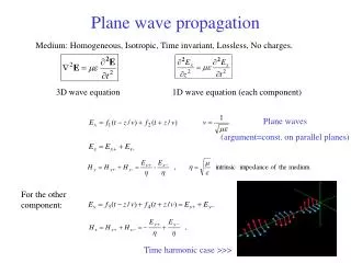
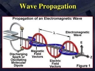
Signal Propagation Propagation in free space is always like light (straight line). Receiving power proportional to 1/d² in vacuum – much more in real environments (d = distance between sender and receiver) Receiving power additionally influenced by fading (frequency dependent) Shadowing (blocking) reflection at large obstacles refraction depending on the density of a medium scattering at small obstacles diffraction at edges refraction shadowing reflection scattering diffraction
Propagation Modes • Ground-wave (< 2MHz) propagation • Sky-wave (2 – 30 MHz) propagation • Line-of-sight (> 30 MHz) propagation
Ground Wave Propagation • Follows the contour of the earth • Can propagate considerable distances • Frequencies up to 2 MHz • Example • AM radio • submarine communication (long waves)
Sky Wave Propagation • Signal reflected from ionized layer of atmosphere back down to earth • Signal can travel a number of hops, back and forth between ionosphere and the earth surface • Reflection effect caused by refraction • Examples • amateur radio • International broadcasts
Line-of-Sight Propagation • Transmitting and receiving antennas must be within line of sight • Satellite communication – signal above 30 MHz not reflected by ionosphere • Ground communication – antennas within effective line of sight due to refraction • Refraction – bending of microwaves by the atmosphere • Velocity of an electromagnetic wave is a function of the density of the medium • When wave changes medium, speed changes • Wave bends at the boundary between mediums • Mobile phone systems, satellite systems, cordless phones, etc.
Line-of-Sight Equations • Optical line of sight • Effective, or radio, line of sight • d = distance between antenna and horizon (km) • h = antenna height (m) (altitude relative to a receiver at the sea level) • K = adjustment factor to account for refraction caused by atmospherics layers; rule of thumb K = 4/3
Line-of-Sight Equations • Maximum distance between two antennas for LOS propagation: • h1 = height of antenna one • h2 = height of antenna two
LOS Wireless Transmission Impairments • Attenuation and attenuation distortion • Free space loss • Atmospheric absorption • Multipath (diffraction, reflection, refraction…) • Noise • Thermal noise
Attenuation • Strength of signal falls off with distance over transmission medium • Attenuation factors for unguided media: • Received signal must have sufficient strength so that circuitry in the receiver can interpret the signal • Signal must maintain a level sufficiently higher than noise to be received without error • Attenuation is greater at higher frequencies, causing distortion (attenuation distortion)
Free Space Path Loss • Free space path loss, ideal isotropic antenna • Pt = signal power at transmitting antenna • Pr = signal power at receiving antenna • = carrier wavelength • d = propagation distance between antennas • c = speed of light (» 3 ´ 10 8 m/s) where d and are in the same units (e.g., meters)
Free Space Path Loss in dB • Free space path loss equation can be recast (decibel version):
Multi-path Propagation Signal can take many different paths between sender and receiver due to reflection, scattering, diffraction Time dispersion: signal is dispersed over time interference with “neighbor” symbols, Inter Symbol Interference (ISI) The signal reaches a receiver directly and phase shifted distorted signal depending on the phases of the different parts multipath pulses LOS pulses signal at sender signal at receiver
Atmospheric Absorption • Water vapor and oxygen contribute most • Water vapor: peak attenuation near 22GHz, low below 15Ghz • Oxygen: absorption peak near 60GHz, lower below 30 GHz. • Rain and fog may scatter (thus attenuate) radio waves. • Low frequency band usage helps.
Effects of Mobility Channel characteristics change over time and location signal paths change different delay variations of different signal parts different phases of signal parts quick changes in the power received (short term fading) Additional changes in distance to sender obstacles further away slow changes in the averagepower received (long term fading) long term fading power t short term fading
Fading Channels • Fading: Time variation of received signal power • Mobility makes the problem of modeling fading difficult • Multipath propagation is a key reason • Most challenging technical problem for mobile communications
Types of Fading • Short term (fast) fading • Long term (slow) fading • Flat fading – across all frequencies • Selective fading – only in some frequencies • Rayleigh fading – no LOS path, many other paths • Rician fading – LOS path plus many other paths
What is Space Wave Propagation? These waves occur within the lower 20 km of the atmosphere, and are comprised of a direct and reflected wave. The radio waves having high frequencies are basically called as space waves. These waves have the ability to propagate through atmosphere, from transmitter antenna to receiver antenna. These waves can travel directly or can travel after reflecting from earth’s surface to the troposphere surface of earth. So, it is also called as Tropospherical Propagation.
. Basically the technique of space wave propagation is used in bands having very high frequencies. E.g. V.H.F. band, U.H.F band etc. At such higher frequencies the other wave propagation techniques like sky wave propagation, ground wave propagation can’t work. Only space wave propagation is left which can handle frequency waves of higher frequencies. The other name of space wave propagation is line of sight propagation.
The space wave follows two distinct paths from the transmitting antenna to the receiving antenna - one through the air directly to the receiving antenna, the other reflected from the ground to the receiving antenna. • The primary path of the space wave is directly from the transmitting antenna to the receiving antenna. So, the receiving antenna must be located within the radio horizon of the transmitting antenna. • Because space waves are refracted slightly, even when propagated through the troposphere, the radio horizon is actually about one-third farther than the line-of-sight or natural horizon.
Although space waves suffer little ground attenuation, they nevertheless are susceptible to fading. This is because space waves actually follow two paths of different lengths (direct path and ground reflected path) to the receiving site and, therefore, may arrive in or out of phase. • If these two component waves are received in phase, the result is a reinforced or stronger signal. Likewise, if they are received out of phase, they tend to cancel one another, which results in a weak or fading signal.
Limitations of space waves As a form of electromagnetic radiation, like light waves, radio waves are affected by the phenomena of reflection, refraction, diffraction, absorption, polarization, and scattering. There are some limitations of space wave propagation: These waves are limited to the curvature of the earth. These waves have line of sight propagation, means their propagation is along the line of sight distance.
Effect of curvature of earth Effect of curvature of earth When the distance between the transmitting and receiving antennas is large, curvature of earth has considerable effect on SWP. The field strength at the receiver becomes small as the direct ray may not be able to reach the receiving antenna. The earth reflected rays diverge after their incidence on the earth. The curvature of earth creates shadow zones.