Chapter 25. Voltammetry Potentiometry : no net current flow 전위차 측정
840 likes | 2.31k Views
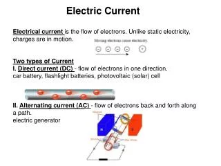
Chapter 25. Voltammetry Potentiometry : no net current flow 전위차 측정 Voltammetry(polarography) : 가전압 resulting current flow measure Polarography ┏ differential pulse polarography ┗ stripping analysis Introduction

Chapter 25. Voltammetry Potentiometry : no net current flow 전위차 측정
E N D
Presentation Transcript
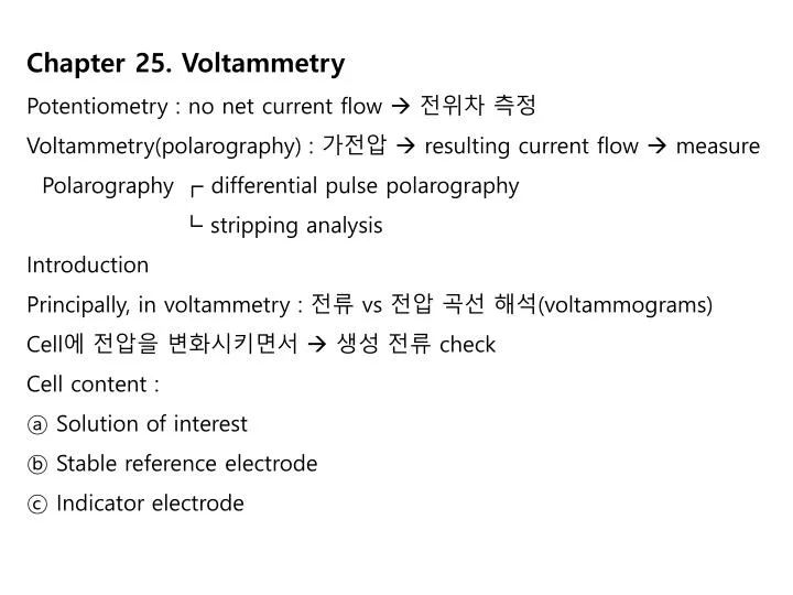
Chapter 25. Voltammetry Potentiometry : no net current flow 전위차 측정 Voltammetry(polarography) : 가전압 resulting current flow measure Polarography ┏ differential pulse polarography ┗ stripping analysis Introduction Principally, in voltammetry : 전류 vs 전압 곡선 해석(voltammograms) Cell에 전압을 변화시키면서 생성 전류 check Cell content : ⓐ Solution of interest ⓑ Stable reference electrode ⓒ Indicator electrode
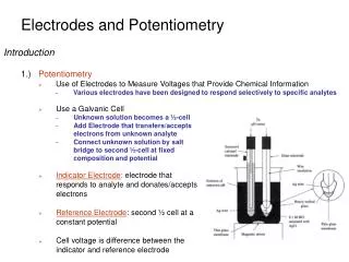
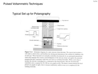
25A Excitation signals in voltammetry Indicator electrode DMC 일 경우 polarography (1922, Heyrovsky가 발명) DME 및 Cell의 구조 Drop rate : constant rate(5-30방울/분) Drop의 life : 2-12sec Voltage scanning rate : 50-200mV/min(DC polarography) 특징 : ① Reproducibility 大 ② Every mercury drop 항상 surface가 새롭다 ③ Electrolytic solu의 양 적게 必要 ④ Hg 대부분 수용액에서 화학적으로 비활성 ⑤ H2의 overvoltage가 크다 ⑥ 많은 종의 화학 종에 관해 연구 가능 단점 ⑦ + 0.4V vs SCE이상의 “+”전위에서 Hg의 anodic dissolution으 로 인해 측정 불가
25B-2 Modified Electrodes: Fig. 25-5
25B-3 Voltammograms Fig. 25-6
25C Hydrodynamic Voltammetry Fig. 25-8
Supporting electrolytes : (0.1M-1.0M정도) 사용이유 : ㉠ Soln.의 저항 감소 ㉡ Electrical field에 의한 전기적 이동이 아니고 Diffusion에 의해서만 전기활성 종이 이동해야한다. 선택:┎ Strong acid : HCl, H2SO4 ┃ Strong based : (NaOH, LiOH) ┃ Neutral salt : (chlorides, perchlorates sulfates of alkali ┃ metal, tetraalkyloammonium ion) ┕ Complexing agents: (tartrate, citrates, cyanides, fluorides, amine)
*Limiting current : 전류 급상승후 전압을 계속 가하여도 전류가 거의 변화하지 않는 부분 • 물질의 전극에 도달하는 속도의 제한을 받기 때문 • 실험 조건 조절하여 확산 속도 만으로 규정되면 • (한계 전류 확산 전류) • Half wave potential : • 확산 전류의 1/2 에 해당하는 전위 물질 확인에 使用 • 잔류 전류의 발생 원인 : • ① 바탕 용액의 존재하는 미량의 불순물의 환원에 기인 • ② 충전 or 축전 전류에 기인 • 용액에 대한 수은 방울에 전하를 띄게 하는 전자의 흐름때문
제거법 : ① Blank의 polarogram을 얻고 시료 용액의 polarogram으로부터 얻어 이 두 확산 전극의 차이 無 ② 보정법 : 분해 전위까지의 polarogram을 직선으로부터 외연장 하는 법 E1/2: half wave potential 확산 전류의 반이 되는 점에서 전위 ij(id) : limiting current residual 과 plateau current 사이의 차 (용액의 속의 활성 중의 농도와 비례) Residual current (charging, condenser current) 어떤 종의 산화-환원 성질의 특징
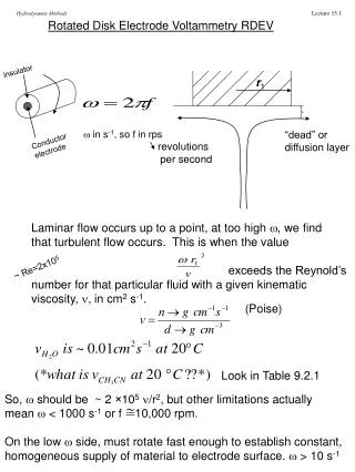
Profiles for Planar Electrodes in Unstirred Solution. Figure 25-9 E-t and I-t curves
Fig 25-10 Concentration distance profiles (diffusion controlled reduction).
Fig. 25-13 Concentration profiles at an electrode/solution interface.
25C-2 Voltammetric currents (Eqs. 25-5,6,7) CoA 0, the current becomes the limiting current, Eq. 25-7 into 25-6 eq. 25-8
25C-3 Oxygen Waves Fig. 25-16
Removal of Oxygen Dissolved oxygen 정량 방해물 분석 전에 제거 O2 + 2H+ + 2e- = H2O2제 1파 H2O2 + 2H+ + 2e- = 2H2O 제 2파 pH7에서 E1/2 = 0--1V vs SCE Air-saturated aqueous solution : 4mM O2 level 5㎂ id유발 제거 방법 : 순수한 He, N2로 5-20분간 용액을 bubble시 N2 tank에 미량 혼입된 O2는 acidic V2+ or Cr2+또는 hot copper의 위를 질소를 통기하므로써 제거
Fig. 25-18 The Clark Oxygen Sensor Cathodic : O2 + 4H+ + 4e- = 2H2O Anodic : Ag + Cl- = AgCl(s) + e-
Rotating Electrodes Voltammetry at rotating Pt Elctrode , 600ppm이상으로 rotating 물질이동 : diffusion & mechanical mixing i1이 diffusion only보다 20배 이상 大 1/2I2...Na2S2O3표준액으로 적정
25D Cyclic Voltammetry Fig. 25-23
Fig. 25-25 Parathion in acetate buffer R-C6H4NO2 + 4e- + 4H+ R-C6H4NHOH + H2O R-C6H4NHOH R-C6H4NO + 2H+ + 2e- R-C6H4NO + 2e- + 2H+ R-C6H4NHOH
Potential sweep triangle form 1-2 sec 內에 sweep완료 (Fig 21-16 참조) 1) 물질을 환원 이 환원종을 다시 산화 A, D 사이의 차 =(2×0.0282/n)V reversible Rate of OX-Red process, mechanism of OX-Red preelec의 연구에 주로 이용
Polarography Ilkovic Equation: Cell을 흐르는 전류 ∝ ① 전극 반응의 속도 Fast ② 전극 표면으로 물질의 이동 속도 Slow 그러므로 limiting current는 물질이동(확산) 속도에 비례 A : 전극의 면적 D : 확산 계수 DME : 실제로 구형 volume : 수은의 유속으로 결정(mg/sec) ∴ A = 0.851(mt)2/3
∴ id : 확산 계수 C : 농도 D : 확산 계수 m : 수은의 유속 t : 수은 방울의 수명
Currents controlled by factor other than Diffusion Diffusion외에 ┏ Charge transfer ┗ Chemical reaction 산화 환원 종의 전극 표면 흡착에 의한 전류 Kinetic current : 전류의 크기가 화학 반응 속도에 의해 통제되는 전류 ex) Catalytic Currents ┏ 1) 전극 부근에서 화학 반응에 의해 다시 가수 분해되 | 는 반응에 의한 전류(촉매 과정에 지배) ┗ 2) 물질의 환원이 촉매가 없을 때 보다 더 “+”에서 일 어날 경우 ex) 1) 2) H ion 의 촉매 환원
Adsorption Current 산화 또는 환원 종이 전극에 흡착 (이 때 전류 크기 : available 전극 표면에 의해 제한) Adsorption prewave 의 height 어떤 특정 농도까지 소극제 농도 小 大 환원 종이 더 이상 흡착되지 않는 곳의 전위에서 제2파 발생 확산 지배 파 1파 + 2파 height 농도에 비례
* Effect of complex formation on pornographic waves Ec, Ea가 영향 complex 생성에 의해 보다 negative (table 21-1참조) Complex reagent의 농도의 함수로 E1/2 K값 결정에 이용 The combining ratio of liquid to metal ion 결정 可
발생 원인 : ① 전극 부근에서 연속적인 stirring ② 흡착 억제 방법 : ① Hg flow 속도를 느리게 ② 지지 전해질의 노도 증가 및 chemical nature 변화 ③ 전극 활성 종의 농도를 낮춘다 ④ 계활성제를 사용(gelatin, 아교, tritonx-100) 계면 활성제에서의 농도 : trial & error 式으로 결정
* Capillary characteristics : capillary constant 에서 maximum
* Temperature D : temperature senstive 2.5%/1℃ Tests for Current-Limiting process Diffusion, kinetic, adsorpton, catalytic currents 구분하는 기준 (1)-(5)에 관계된 파고의 변화 (1) 전극 활동 종의 농도 (2) Hg 압력(수은 주의 높이를 변화) (3) pH (4) Buffer 농도 (5) 온도(촉매, kinetic 포함)
(1) 농도에 대한 한계 전류의 관계 Fig 3.6 참조(A) (B), (C) -> 흡착, 촉매 전류와의 관계 (2) 수은 주 높이를 변화 Fig 3.7참조 전류가 농도에 무관한 농도에서 측정해야 한다