Load Cell
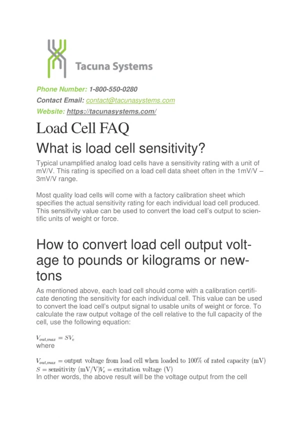
Load Cell. The load cell is a type of force transducer. It changes the applied force to an electrical signal that must be read by another device.


Load Cell
E N D
Presentation Transcript
Load Cell • The load cell is a type of force transducer. It changes the applied force to an electrical signal that must be read by another device. • The load cell system the second part of the program loop algorithm, it measures the force applied by the actuator. This loop between the load cell and the actuator tells the actuator to apply more or less force to the test specimen. • The load cell that we are using uses a 6-line cable which consists of a Excitation +/-, Signal +/-, and Sense +/-. • Excitation is simply the input voltage (up to 18V) • Signal is the output voltage in 2 mV/V • Sense is the input voltage control. It makes sure the input voltage to the excitation is constant regardless of the change in internal resistance
Load Cell • Futek Rod End load cell – rated 2000 lbs with a 6-wire receptacle
Load Cell • Load Cell Circuit
Strain Gauge • The strain on the specimen in the primary purpose of this experiment. • The strain gauge will not be directly on the specimen as the experiment will be used at up to 1000 degrees Celsius. At this point, the strain gauge itself temperatures would break down from heat exhaustion, so we will use a strain gauge with extended leads to measure the strain on the specimen.
Strain Gauge • The strain gauge essentially functions as a variable resistor. The change in this is measured using a Wheatstone bridge formation. • The resistors on the independent side of the strain gauge must be of the same value, while the resistor on the same side as the strain gauge component must have the same resistance as the initial resistance of the strain gauge. • As the specimen changes due to outside forces and conditions, the resistance of the strain gauge will change and there will be a voltage read on the voltmeter. This goes into an equation that determines the motion of the strain gauge.
Power Supply • System requires a minimum output of 12V to 20A • Large power output and because of the scope of the project, we decide to use multiple power sources.