Download
1 / 41
430 likes | 712 Views
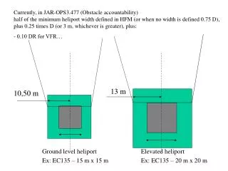
Heliport Perimeter Lighting Research, Findings, Future Prospects. Airport Technology Transfer Conference, Atlantic City 2010 Robert Bassey, FAA. Vertical Flight. Advisory Circular (AC) 150/5390-2B provides guidance for illuminating the heliport landing and taxi areas. Vertical Flight.

E N D
Heliport Perimeter LightingResearch, Findings, Future Prospects Airport Technology Transfer Conference, Atlantic City 2010Robert Bassey, FAA
Vertical Flight • Advisory Circular (AC) 150/5390-2B provides guidance for illuminating the heliport landing and taxi areas
Vertical Flight • The AC details the requirements in respect to the color, number and spacing of heliport perimeter lights at the Touchdown and Liftoff (TLOF) area and the Final Approach and Takeoff (FATO) area • The operational specifications for the perimeter lighting fixture are not stated
Vertical Flight • A research effort was initiated by the Federal Aviation Administration (FAA) to define the operational specifications and performance criteria for heliport perimeter lighting • To support this initiative the FAA Williams J Hughes Technical Center (WJHTC) Heliport was fully refurbished to be representative of heliports around the country
Vertical Flight A pilot has to execute many difficult tasks when approaching a heliport at night, including: • acquiring the heliport lighting patterns from the surrounding ambient lighting environment • determining and controlling the descent rate using information from the immediate environment • judging and controlling the closure rate of the aircraft to the heliport in the final approach
Vertical Flight • The heliport perimeter lighting is intended to be the cue that pilots use to acquire the heliport • To be effective the lighting should enable the pilot to both establish the position of the heliport and identify the outline shape
FAA WJHTC Flight Trials • The research initiative comprised a number of nighttime flight trials at the FAA WJHTC Heliport in Visual Meteorological Conditions (VMC) • The trials were used to establish the applicable intensity and coverage of the heliport perimeter lighting fixtures
FAA WJHTC Flight Trials • During the flight trials certain assumptions were made, namely that: • The heliport lighting is the predominant visual feature • The fixture is considered to be a point source • The visibility is uniform vertically, as well as horizontally • The atmosphere is not significantly spectrally selective over the distances involved
FAR Requirements • The minimum operating visibility and cloud base that was assumed is three miles and 1200 feet to meet Federal Aviation Regulations (FAR) Part 91.155 requirements for basic Visual Flight Rules (VFR) weather minimums Part 91.155 (b) Class G Airspace. Notwithstanding the provisions of paragraph of this section, the following operations may be conducted in Class G airspace below 1,200 feet above the surface: (1) Helicopter. A helicopter may be operated clear of clouds if operated at a speed that allows the pilot adequate opportunity to see any air traffic or obstruction in time to avoid a collision Airspace Flight Visibility Class G, Night 3 statute miles
FAA WJHTC Flight Trials • The aircraft used was the FAA WJHTC Sikorsky S-76A helicopter operated by two FAA pilots
FAA WJHTC Flight Trials • Weather for the evening was 5 MPH winds, visibility 9 statute miles and clear with moonlight horizon • For each run the pilots were instructed to proceed out to 11 statute miles, turn and start an approach to the heliport • When a steep approach was required, the start point was at a range of five statutemiles from the heliport
FAA WJHTC Flight Trials • The profile flown during each approach was representative of a normal helicopter approach in VMC conditions • During each run the pilot reported the range at which the perimeter lighting became visible and then when the lighting became usable as a final approach cue • An onboard data collection system was used to collect data on helicopter speed, heading and the vertical approach path for each run
FAA WJHTC Flight Trials • The onboard data collection system was used to estimate the pitch, roll and yaw attitude of the helicopter • Comments were elicited from the subject pilots on the color of the perimeter light so as to determine if the perimeter lights appeared green in color
Specifying Heliport Lighting Chromaticity • Photometric testing was conducted at the FAA WJHTC Photometric Laboratory on several heliport lighting fixtures • The chromaticity coordinates of the fixtures were evaluated using a Photo Research PR-655 SpectraScan Spectroradiometer • Individual fixtures were tested using the LSI photometric system to determine the luminous intensity and beam spread characteristics
Specifying Heliport Lighting Chromaticity • The resulting chromaticity results were compared with the International Commission on Illumination (CIE) chromaticity coordinate system to determine where the coordinates fall in relation to the FAA’s aviation color boundaries for signal colors • These coordinates were plotted on the CIE chart • Ultimately the data collected will be used to define the acceptable chromaticity boundary limits for green heliport perimeter lights
Specifying Heliport Lighting Intensity The four main factors that were used to determine the intensity of lighting required are: • The ambient lighting environment • The helicopter approach angles • The meteorological conditions in which it is required • The range at which the signal needs to be seen
Specifying Heliport Lighting Intensity Ambient lighting environment • The eye threshold of illuminance is the minimum amount of perceived brightness required for an observer to detect a visual cue with a high degree of certainty • The relationship between illuminance thresholds and background luminance for steady burning point sources for about 98 percent probability of detection have been established and referenced in the NBS monograph 159 “Visual Range: Concepts, Instrumental Determination, and Aviation Applications”, by C. A. Douglas and R. L. Booker, June 1977
Illuminance Threshold versus Background Luminance98 percent probability of detection
Specifying Heliport Lighting Intensity Meteorological conditions • For the light to be easy to find the identified illuminance, threshold values are to be increased by a factor of 10 • Therefore the eye threshold of illuminance for a clear, moonlight background horizon is inferred to be 0.79432 • Given the meteorological visibility, the eye illumination threshold and the required viewing range, Allard’s law was used to compute the intensity of a steady light that is necessary
Specifying Heliport Lighting Intensity Helicopter approach angles • Helicopter approaches are subject to variability in terms of their vertical and horizontal profiles • The distribution of intensity of the perimeter lighting as a function of elevation should be such that the lighting is bright enough to be seen at the required range (lower elevation angles)without glare or dazzle at closer ranges (higher elevation angles)
Specifying Heliport Lighting Intensity Helicopter approach angles • Given that approaches to heliports are typically performed into the wind, helicopters can in principle approach the heliport from any direction • Consequently the specified intensity for heliport perimeter lighting must be maintained for all angles of azimuth
Specifying Heliport Lighting Intensity Helicopter approach angles • According to Flight standards typical vertical approach paths used by helicopters making approaches to a heliport (assuming VMC conditions)
Specifying Heliport Lighting Intensity • Allard’s law was used to compute the intensity of a steady light that would be detectable. • The equation to define Allard’s law is: E = (I/[R^2]) x (℮^-σR) Where E = Eye Illuminance Threshold (lux) I = Luminous intensity of the light unit (candelas) σ = Extinction coefficient (m^-1) R = Visual range of the light (m)
Specifying Heliport Lighting Intensity Range of Signal • The assumed VMC operating minima being used for the evaluation comprises of a minimum operating visibility of 3 miles and a minimum decision range of 2 miles • Applying these values for usable range and meteorological visibility, together with a value of 0.79432 for eye illumination threshold to Allard’s law yields an intensity of 23 candelas • This value of intensity should be maintained for elevations from 3 to 10 degrees above the horizontal (i.e. the main beam)
Specifying Heliport Lighting Intensity Range of Signal • Higher elevation angles are encountered at shorter viewing ranges where less intensity is required to achieve the same level of conspicuity directed at 2 miles • A usable range of 1.5 miles is assumed for coverage above 10 degrees • Applying this values for usable range to Allard’s law yield’s an intensity of 8 candelas • The main beam should roll off smoothly down to this value without marked discontinuity
Validation of Initial Findings • The specification that has been described has been derived from empirical and theoretical studies • It is therefore necessary to validate the specification with a large pilot population and in varied ambient lighting conditions before incorporating it in the FAA Advisory Circular • Additional nighttime flight trials will be conducted at the Altru Hospital test helipad in Grand Forks, North Dakota by personnel from University of North Dakota (UND) Aerospace
Validation of Initial Findings • The additional flight trials will be conducted in background horizons to include overcast skies with moon and deep twilight as well as a variation of approach angles • High risk approaches will be flown using an Unmanned Aircraft System (UAS) helicopter • Acquisition range and applicable intensity data will be compiled
Next Steps • Using the assembled data, the mean and standard deviation of the required intensity values at the varied background horizons will be calculated • Taking into account the performed calculations, propose the revised (mean) intensity requirementsacross the identified elevations (i.e. vertical intensity distribution) as the minimum intensity standards for heliport perimeter lighting
Next Steps • Flight trials will be conducted at heightened perimeter light intensities to investigate a precautionary upper limit on the perimeter light intensity in order to avert glare • Once validated, the intensity distribution and chromaticity specifications will be recommended for incorporation into the FAA Advisory Circular for Heliport Design
Questions or Comments? Donald.Gallagher@faa.gov, Visual Guidance Program Mgr. Robert.Bassey@faa.gov, Visual Guidance Project Mgr. www.airporttech.tc.faa.gov FAA William J. Hughes Technical Center Airport Safety Technology R&D AJP-6311, Building 296 Atlantic City International Airport, NJ 08405