Download
1 / 15
150 likes | 474 Views
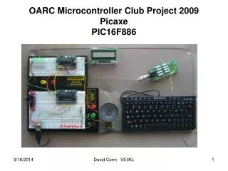
OARC Microcontroller Club Project 2009 Picaxe PIC16F886. PIC Project C Programming PIC16F887. Develpoment Board. Programmer. PC. Transmitter. Dummy Load/Power Meter. Using Picaxe EEPROM 256 Bytes. Used with the Keyboard Used with the Power Meter

E N D
OARC Microcontroller Club Project 2009PicaxePIC16F886 David Conn VE3KL
PIC Project C ProgrammingPIC16F887 Develpoment Board Programmer PC Transmitter Dummy Load/Power Meter David Conn VE3KL
Using Picaxe EEPROM256 Bytes • Used with the Keyboard • Used with the Power Meter • EEPROM stores data that can be retrieved David Conn VE3KL
EEPROM 256 Bytes in Picaxe Put data in EEPROM with the command: EEPROM location,(data,data...) Example: EEPROM 0,(66,12,0,0,0,”V”) means The number 66 is stored in location 0 of the EEPROM 12 is stored in location 1 zero's stored in locations 2,3,4 Ascii “V” is stored in location 5 ------------------------------------------------------------------- ;Read from EEPROM read 0,b1 put 66 into variable b1 read 5,b2 puts “V” into variable b2 David Conn VE3KL
The Normal way to use EEPROM(Write 16 lines by 16 Bytes) EEPROM $00,(0,0,0,0,0,0,0,0,0,0,0,0,0,0,0,0) EEPROM $10,(0,0,0,0,0,0,0,0,0,0,0,0,0,0,0,0) EEPROM $20,(0,0,0,0,0,0,0,0,0,0,0,0,0,0,0,0) EEPROM $30,(0,0,0,0,0,0,0,0,0,0,0,0,0,0,0,0) EEPROM $40,(0,0,0,0,0,0,0,0,0,0,0,0,0,0,0,0) EEPROM $50,(0,0,0,0,0,0,0,0,0,0,0,0,0,0,0,0) EEPROM $60,(0,0,0,0,0,0,0,0,0,0,0,0,0,0,0,0) EEPROM $70,(0,0,0,0,0,0,0,0,0,0,0,0,0,0,0,0) EEPROM $80,(0,0,0,0,0,0,0,0,0,0,0,0,0,0,0,0) EEPROM $90,(0,0,0,0,0,0,0,0,0,0,0,0,0,0,0,0) EEPROM $A0,(0,0,0,0,0,0,0,0,0,0,0,0,0,0,0,0) EEPROM $B0,(0,0,0,0,0,0,0,0,0,0,0,0,0,0,0,0) EEPROM $C0,(0,0,0,0,0,0,0,0,0,0,0,0,0,0,0,0) EEPROM $D0,(0,0,0,0,0,0,0,0,0,0,0,0,0,0,0,0) EEPROM $E0,(0,0,0,0,0,0,0,0,0,0,0,0,0,0,0,0) EEPROM $F0,(0,0,0,0,0,0,0,0,0,0,0,0,0,0,0,0) ; In the above, all the data is zero ; the location is written in Hex ; Note that $10 corresponds to decimal 16 … 16 numbers per line! David Conn VE3KL
EEPROM Practice Files • eeprom_simple_test.bas • eeprom_simple_test1.bas David Conn VE3KL
EEPROM with Keyboard Example: the scan code for the Key “A” is $1C main: Kbin [1000,main], b1 ;get scan code. Put into variable b1 read b1,b2 ;read from the EEPROM debug goto main ; All data set to zero except the “A” at location $1C EEPROM $00,(0,0,0,0,0,0,0,0,0,0,0,0,0,0,0,0) EEPROM $10,(0,0,0,0,0,0,0,0,0,0,0,0,”A”,0,0,0) EEPROM $20,(0,0,0,0,0,0,0,0,0,0,0,0,0,0,0,0) EEPROM $30,(0,0,0,0,0,0,0,0,0,0,0,0,0,0,0,0) EEPROM $40,(0,0,0,0,0,0,0,0,0,0,0,0,0,0,0,0) EEPROM $50,(0,0,0,0,0,0,0,0,0,0,0,0,0,0,0,0) EEPROM $60,(0,0,0,0,0,0,0,0,0,0,0,0,0,0,0,0) EEPROM $70,(0,0,0,0,0,0,0,0,0,0,0,0,0,0,0,0) EEPROM $80,(0,0,0,0,0,0,0,0,0,0,0,0,0,0,0,0) EEPROM $90,(0,0,0,0,0,0,0,0,0,0,0,0,0,0,0,0) EEPROM $A0,(0,0,0,0,0,0,0,0,0,0,0,0,0,0,0,0) EEPROM $B0,(0,0,0,0,0,0,0,0,0,0,0,0,0,0,0,0) EEPROM $C0,(0,0,0,0,0,0,0,0,0,0,0,0,0,0,0,0) EEPROM $D0,(0,0,0,0,0,0,0,0,0,0,0,0,0,0,0,0) EEPROM $E0,(0,0,0,0,0,0,0,0,0,0,0,0,0,0,0,0) EEPROM $F0,(0,0,0,0,0,0,0,0,0,0,0,0,0,0,0,0) David Conn VE3KL
Keyboard & EEPROM Practice Files • keyboardscancode.bas • keyineepromtable.bas David Conn VE3KL
Power Meter VE3KL 16 Watt Dummy Load/Power Meter Elecraft DL1 minimodule 20 Watt Dummy Load/Power Meter Elecraft David Conn VE3KL
Power Meter Block Diagram Picaxe Analog Input EEPROM Dummy Load Detector 0 to 5 Volts DC Transmitter CW 10 Watts Diode Detector . Detects RF from TX DC fed to ADC of Picaxe (0 to 255) Picaxe looks up power level from EEPROM Power out displayed in Watts EEPROM values calculated from a formula I2C Display David Conn VE3KL
Power Meter Circuit10 Watts Max R=25 Ohms C=0.01 uF D1: 1N5711 D2: 1N914 R1 20K R2 10 K +5 Volts D1 R D2 Picaxe Analog Input (Pin 19) EEPROM RF Input C R1 R I2C Display R2 David Conn VE3KL
The Formula Pin = (10/255^2)*bo^2 bo is the A/D variable read in to the Picaxe This formula is written into the EEPROM See the program supplied David Conn VE3KL
Program Flow PowerMeter_template.bas ; program flow ; set up i2c slave for display ; adc into b0 ; read power from EEPROM ; use bintoascii to separate the power numbers ; write to the display ; loop David Conn VE3KL
Power Meter Calibration • Adjust R2 to give proper reading compared to a power meter standard • Do this for several frequencies up to 500 MHz • Put correction factor in program • Use simple keypad to select the band of operation.
73 Dave VE3KL • Work lots of DX • Build stuff • Attend flea markets and hope for a following wind