EEG Machine
EEG Machine . By The All-American Boys Featuring Slo -Mo Motaz Alturayef Shawn Arni Adam Bierman Jon Ohman. Project Goals. Goals: Design an EEG ( Electroencephalography) machine to promote the generation of user selected brainwave frequencies


EEG Machine
E N D
Presentation Transcript
EEG Machine By The All-American Boys Featuring Slo-Mo MotazAlturayef Shawn Arni Adam Bierman Jon Ohman
Project Goals • Goals: • Design an EEG (Electroencephalography) machine to promote the generation of user selected brainwave frequencies • Accesible Frequency ranges (Theta, Alpha, Beta) • Using Audio and Video Feedback to synchronize brain
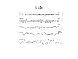
Physiology of Neurofeedback • Brain waves divided into distinct frequency bands: • Delta: 0-3 Hz, Associated with slow wave sleep • Theta: 4-7 Hz, Associated with drowsiness or arousal • Alpha: 8-13 Hz, Associated with relaxed concentration or contentment • Beta: 14-30 Hz, Associated with intense concentration, high levels of thought activity
Physiology Continued • Synchronization of Brain waves is possible • External stimuli used to synchronize brain wave frequencies • Our project will use both audio and video stimuli to synchronize waves • Can be used to train an individual to put themselves in desired state
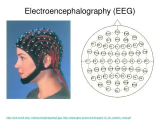
Electrode Input Design • Five electrode two channel EEG headband for signal monitoring • Design compiled from multiple schematics • Using active electrodes • Powered either with lithium batteries or hard line to main board • Small voltage values require ultra low noise devices
Amplification, Filtering, and A/D • Done at main board • Amplifier strengthens microvolt signals to usable levels • Signal passes through low-pass and high pass filters to remove DC components and higher frequency noise and brain waves • Possibly sent through band-pass filters as well • Digitized using low noise A/D converter
Design Aspects • Low signal levels require very low noise devices • Battery powering could introduce too much signal noise unless properly shielded • Two channels sufficient to measure frequency content • Differential voltage measurements • Fifth electrode along scalp midline to create unbiased ground
Risks • Too much noise in system • Will distort signal and render it useless • Can use commercial electrodes, conductive paste • Filters should assist in removing noise, also use shielding techniques for battery and twisted pairs for wires • Two channels insufficient for measurement • Possible to build more channels • Filters drop off too shallowly to isolate bands • Only a problem if band-pass filtering is employed (Additional Feature)
Physiological Effects of Outputs • Alter brain frequency through external stimulus • Auditory stimulus is most effective • Produce a stimulating frequency equal to that of the desired brain frequency state • Binaural beats: Auditory processing artifacts, the perception of which arises in the brain independent of physical stimuli • Visual stimulus is another common option • A screen or monitor flashes an image at the rate of the desired brain frequency state
Memory Options • Two types • RAM (Volitile) • ROM (Non-Volitile) • SD Card Flash • Easy to load • Board Mounted Flash • More permanent
Spansion Memory • 8 MBIT Storage • 3.0V Supply • No Bus Contention • Memory controller in Altera FPGA • Controller allows access to program and read data from memory • Controller will also transfer data to audio/video controller for output
Risks • Not enough room in Flash for both audio and video signals • Can revert to SD Card where more space is available • High risk of epileptic seizures with a flashing monitor • Warning must be presented • Auditory signal can be used exclusively
PC : (Matlabor LabView) • Analyze the brainwave for frequency content and find the dominant frequency. Two Approaches of doing this: • Signal as a whole and do Power Spectral Density (PSD) analysis. • Divide the signal into 4 frequency bands then do PSD. • Risks • Not being able to debug the code with real brainwave signals. • Synchronising the PC output with the whole system.
Altera DE2 Development Board I/O needs Readily available 32-bit Nios II embedded processor & SOPC Builder – configuration & integration Quartus II - Scalable environment
DE2 Risks • Risks • Too much reliance on built-in features • Input data usable? (ADC conversion) • Potential usage of development board’s many options may spread team too thin • Alternate choice – MSP430
Processor Testing • Input Signals • User Input on LEDs • Verify Electrode/ADC sample and store, as audio output • Check DF result and store using 7-segment displays/LEDs • Show difference between UI and DF on LED/7 segment
Processor Testing • Output Signal • Stored Electrode/ADC signal to PC, output as audio on PC • Wait State • Between samples illuminate LED
Schedule • See Microsoft Project