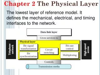
Chapter 2 The Physical Layer
Chapter 2 The Physical Layer. Data Communication. Information can be transmitted on wires by varying some physical property such as voltage , current or light .


Chapter 2 The Physical Layer
E N D
Presentation Transcript
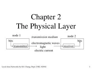
Chapter 2 The Physical Layer
Data Communication • Information can be transmitted on wires by varying some physical property such as voltage, current or light. • By representing the value of this voltage or current as a single-valued function of time, f(t), we can model the behavior of the signal and analyze it mathematically. computer 2 computer 1 bits bits transmission medium transmitter receiver • electric current • light • electromagnetic waves
Signal Analysis Using Fourier Series Any reasonably behaved periodic function, g(t), with period T can be constructed by summing a (possibly infinite) number of sines and cosines: where f=1/T is the fundamental frequency and an and bn are the sine and cosine amplitudes of the nth harmonics.
Example : Digital Signal Analysis Digital Signal Spectral Analysis
Digital Signal Synthesis One harmonic Two harmonics
Four harmonics Eight harmonics
Maximum Data Rate or Capacity of a Communication Channel 1. Noiselss Channel Case : Nyquist’s Theorem Maximum capacity ( C ) = 2 H log2 V bits/sec number of signal levels bandwidth
Maximum Data Rate or Capacity of a Communication Channel 2. Noisy Channel Case: Shannon’s Theorem If random noise is present, the situation deteriorates rapidly. The amount of thermal noise present is measured by the ratio of the signal power to the noise power, called the signal-to-noise ratio (S/N). Maximum Capacity ( C ) =H log2(1+S/N)
signal + noise signal noise High SNR t t t noise signal + noise signal Low SNR t t t Average Signal Power SNR = Average Noise Power SNR (dB) = 10 log10 SNR
Numerical Example 1: 2. Noisy channel case: Bandwidth H = 3000 Hz Voltage Levels V = 4 S/ N = 20 dB 20 = 10 log 10 (S/ N) S/ N = 100 Then, C = H log 2 ( 1 + S/N ) = = 3000 log 2 (1 + 100) = 19800 bps. 1. Noiseless channel case: Bandwidth H = 3000 Hz Voltage Levels V = 4 ( two binary bits) Then, C = 2H log 2 (V) = 2 * 3000 log 2 (4) bps. = 12000 bps.
Numerical Example 2: 2. Noisy channel case: Bandwidth H = 3000 Hz S/ N = 20 dB Then, 20 = 10 log 10 (S/ N) S/ N = 100 C = H log 2 ( 1 + S/N ) = = 3000 log 2 (1 + 100) = 19800 bps. 1. Noiseless channel case: Bandwidth H = 3000 Hz Voltage Levels V = 8 ( three binary bits) Then, C = 2H log 2 (V) = 2 * 3000 log 2 (8) bps. = 18000 bps.
Transmission Media Transmission medium:: the physical path between transmitter and receiver. • Guided media:: waves are guided along a physical path (e.g, twisted pair, coaxial cable and optical fiber) • Unguided media :: means for transmitting but not guiding electromagnetic waves (e.g., the atmosphere and outer space).
Guided Transmission Data • Magnetic Tapes • Coaxial Cable • Twisted Pair • Fiber Optics
Magnetic Tapes Bandwidth: A tape can hold 7 gigabytes. A box can hold about 1000 tapes. Assume a box can be delivered in 24 hours. The effective bandwidth=7*1000*8/86400=648 Mbps Cost Cost of 1000 tapes= $5000. If a tape can be reused 10 times and the shipping cost is $ 200, we have a cost of $ 700 to ship 7000 gigabytes.
Coaxial Cables Types 10Base5 Thick Ethernet :: thick (10 mm) coax 10 Mbps, 500 m. max segment length, 100 devices/segment, awkward to handle and install. 10Base2 Thin Ethernet :: thin (5 mm) coax 10 Mbps, 185 m. max segment length, 30 devices/segment, easier to handle,
Coaxial Cable Applications • Television distribution • Ariel to TV • Cable TV • Long distance telephone transmission • Can carry 10,000 voice calls simultaneously • Being replaced by fiber optic • Short distance computer systems links • Local area networks
Twisted Pair Cables • Unshielded Twisted Pair (UTP) • Ordinary telephone wire • Cheapest • Easiest to install • Suffers from external EM interference • Shielded Twisted Pair (STP) • Metal braid or sheathing that reduces interference • More expensive • Harder to handle (thick, heavy)
UTP Categories (a). Category 3 UTP. (b). Category 5 UTP.
UTP Categories • Cat 3 • up to 16MHz • Voice grade found in most offices • Twist length of 7.5 cm to 10 cm • Cat 5 • up to 100MHz • Commonly pre-installed in new office buildings • Twist length 0.6 cm to 0.85 cm
Twisted Pair Applications • Most common medium • Telephone network • Between house and local exchange (subscriber loop) • Within buildings • To private branch exchange (PBX) • For local area networks (LAN) • 10Mbps or 100Mbps
10BASE-T 10 Mbps baseband transmission over twisted pair. Two Cat 3 cables, Manchester encoding, Maximum distance - 100 meters Ethernet hub
Fiber Optics • Optical fiber :a thin flexible medium capable of conducting optical rays. Optical fiber consists of a very fine cylinder of glass (core) surrounded by concentric layers of glass (cladding). • a signal-encoded beam of light (a fluctuating beam) is transmitted by total internal reflection. • Total internal reflection occurs in the core because it has a higher optical density (index of refraction) than the cladding.
Fiber Cables (a). Side view of a single fiber. (b). End view of a sheath with three fibers.
Total Internal Reflection (a). Three examples of a light ray from inside a silica fiber impinging on the air/silica boundary at different angles. (b). Light trapped by total internal reflection.
Fiber Optic Networks A fiber optic ring with active repeaters.
Optical Fiber - Benefits • Greater capacity (Gbps) • Smaller size & weight • Lower attenuation • Electromagnetic isolation • Greater repeater spacing ( 10s of Km)
Optical Fiber - Applications • Long-haul trunks • Metropolitan trunks • Rural exchange trunks • Subscriber loops • LANs
Optical Fibers Devices • Light Emitting Diode (transmitter) • Cheaper • Wider operating temp range • Last longer • Used with multimode fiber optics • Injection Laser Diode (transmitter) • More efficient • Greater data rate • Used with single mode fiber optics • PIN Photo-Diode (Receiver)
Wireless Transmission • The Electromagnetic Spectrum • Radio Transmission • Microwave Transmission • Infrared and Millimeter Waves • Lightwave Transmission
Electromagnetic Waves one cycle speed=frequency wavelength m/s=cycles/s m/cycles Hz(hertz) speed of light (in vacuum)=
Wireless Transmission Frequencies • 2GHz to 40GHz ( Microwave, Satellite) • 30MHz to 1GHz ( Broadcast radio ) • 3 x 10¹¹ to 2 x 10¹⁴ ( Infrared) ISM (Industrial/Scientific/Medical) Band Transmitters using these bands do not require government licensing. One band is allocated worldwide: 2.400-2.484 GHz. In addition, in the US and Canada, bands also exist from 902-928 MHz and from 5.725-5.850 GHz. These bands are used for cordless telephones, garage door openers, wireless hi-fi speakers, security gates, etc.
Antennas • Electrical conductor used to radiate or collect electromagnetic energy. Same antenna often used for both transmission and reception • Transmission • Radio frequency energy from transmitter • Converted to electromagnetic energy by antenna • Radiated into surrounding environment • Reception • Electromagnetic energy impinging on antenna • Converted to radio frequency electrical energy • Fed to receiver
Radio Transmission • Radio waves are easy to generate, can travel long distance, and penetrate buildings easily, so they are widely used for communication, both indoors and outdoors. • Radio waves are also omnidirectional, meaning that they travel in all directions from the source, so that the transmitter and receiver do not have to be carefully aligned physically.
Radio Transmission (a). In the VLF, LF, and MF bands, radio waves follow the curvature of the earth. (b). In the HF band, they bounce off the ionosphere.
Microwave Transmission • Above 100 MHz, the waves travel in straight lines and can therefore be narrowly focused. Concentrating all the energy into a small beam using a parabolic antenna gives a much higher signal to noise ratio. • Since the microwaves travel in a straight line, if the towers are too far apart, the earth will get in the way. Consequently, repeaters are needed periodically.
Disadvantages: • do not pass through buildings well • multipath fading problem (the delayed waves cancel the signal) • absorption by rain above 8 GHz • severe shortage of spectrum • Advantages: • no right way is needed (compared to wired media) • relatively inexpensive • simple to install
Infrared and Millimeter Transmission . Unguided infrared and millimeter waves are widely used for short-range communication. The remote controls used on televisions, VCRs, and stereos all use infrared communication. . They are relatively directional, cheap, and easy to build, but have a major drawback: they do not pass through solid objects. . This property is also a plus. It means that an infrared system in one room will not interfere with a similar system in adjacent room. It is more secure against eavesdropping.
Convection currents can interfere with laser communication systems. A bidirectional system with two lasers is pictured here.
Communication Satellites • Satellite is relay station • Satellite receives on one frequency, amplifies or repeats signal and transmits on another frequency • Types based on orbital altitude: • Geostationary Orbit Satellites (GEO) • Medium-Earth Orbit Satellites (MEO) • Low-Earth Orbit Satellites (LEO) • Applications : Television, Long distance telephone, Private business networks
Satellites Types Communication satellites and some of their properties, including altitude above the earth, round trip delay time and number of satellites needed for global coverage.
Satellites versus fiber cables • High bandwidth available for individual users. • More suitable for mobile communication • Naturally suited for broadcast applications • Better suited for connecting remote areas.