Download
1 / 18
180 likes | 384 Views
LCLS. LCLS Longitudinal Feedback and Stability Requirements P. Emma LLRF Review November 23, 2005. Critical LCLS Accelerator Parameters. Final energy 13.6 GeV (stable to 0.1%) Final peak current 3.4 kA (stable to 12% ) Transverse emittance 1.2 m m (stable to 5%)

E N D
LCLS LCLS Longitudinal Feedback and Stability Requirements P. Emma LLRF ReviewNovember 23, 2005
Critical LCLS Accelerator Parameters • Final energy 13.6 GeV (stable to 0.1%) • Final peak current 3.4 kA (stable to 12%) • Transverse emittance 1.2 mm (stable to 5%) • Final energy spread 10-4 (stable to 10%) • Bunch arrival time (stable to 150 fs) (stability specifications quoted as rms)
FEL Power Sensitivity to e- Beam 12% DIpk/Ipk 20% DP/P 0.1% DE/E 0.2% Dlr/lr
Electron Bunch Compression d DE/E d d under-compression szi ‘chirp’ z z z sz sdi Dz = R56d V = V0sin(kz) RF Accelerating Voltage Path-Length Energy- Dependent Beamline
d RF phase jitter becomes bunch length jitter… Compression factor: Df Compression Stability d z
Machine Schematic with Parameters 250 MeV z 0.19 mm 1.6 % 4.30 GeV z 0.022 mm 0.71 % 13.6 GeV z 0.022 mm 0.01 % 6 MeV z 0.83 mm 0.05 % 135 MeV z 0.83 mm 0.10 % Linac-X L =0.6 m rf= -160 rf gun Linac-1 L 9 m rf -25° Linac-2 L 330 m rf -41° Linac-3 L 550 m rf 0° 23-m Linac-0 L =6 m undulator L =130 m 21-1b 21-1d 21-3b 24-6d 25-1a 30-8c X ...existing linac BC1 L 6 m R56 -39 mm BC2 L 22 m R56 -25 mm DL1 L 12 m R56 0 LTU L =275 m R56 0 1 X-klys. 3 klystrons 1 klystron 26 klystrons 45 klystrons research yard SLAC linac tunnel
Correlated or Uncorrelated Errors? Suppose the mean RF phase of all 26 Linac-2 klystrons changes by: 0.21° |DIpk/Ipk| 12% This may arise statistically with 26 random uncorrelated phase errors with rms spread of: f21/2 = 0.21°261/2 = 1.07°, or with 26 identical phaseerrors. Since we don’t fully understand the correlations, we choose the conservative (smallest) tolerance of 0.21° rms/klys.and then reduce this by ~N, where N (=12) is the number of major error sources.
0.50 X- X-band Longitudinal Fast-Jitter Tolerance Budget tolerances are rms values laser timing (w.r.t. RF) laser energy mean phase of 2 klys. 1 klys. 1 X-klys. mean phase of 26 klys. mean phase of 45 klys. mean amp. of 2 klys. 1 klys. 1 X-klys. mean amp. of 26 klys. mean amp. of 45 klys.
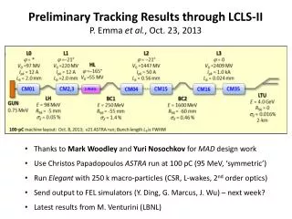
Jitter Simulations (Particle Tracking) 0.09% 0.004% Lg 96 fs Pout 10%
sz1 sz2 V0 d0 gun BPM d3 d1 d2 L0 1 2 V1 V2 V3 L2 L3 X L1 DL2 DL1 BC1 BC2 CSR detector LCLSLongitudinal Beam-Based Feedback (stabilizes beam for jitter frequencies < 10 Hz @ 120-Hz rep-rate) J. Wu, et al., PAC’05, May 16-20, 2005, Knoxville, TN.
CSR Relative Bunch Length Monitor Red curve: Gaussian Black curve: Uniform Blue curve: ‘Real’ J. Wu, et al., PAC’05, May 16-20, 2005, Knoxville, TN.
feedback on DIpk/Ipk0 (%) LCLS Feedback Performance (use CSR P/P) feedback off J. Wu (undulator entrance)
Feedback System Bode Plot at 120 Hz J. Wu • Define fast-jitter as variations faster than 2 seconds • Slow drift occurs on time-scales > 2 seconds (to 24+ hr)
Slow Drift Tolerance Limits (Top 4 rows for De/e < 5%, bottom 4 limited by feedback dynamic range) (Tolerances are peak values, not rms) * for synchronization, this tolerance might be set to 1 ps (without arrival-time measurement)
Compensate X-band Phase Step Error... jx(deg) x-band phase LX phase error = 5o final energy final peak current L1 adjustment: phase +2.1o, voltage -2.1% final arrival time J. Wu
E E Dtf E = E0 E = E0 E > E0 Dt0 Dt0 t t Gun Timing Jitter and Energy Feedback Dtf= Dt0 without energy feedback with energy feedback