Download
1 / 10
100 likes | 235 Views
This document outlines the architecture and requirements of the Low-Level Radio Frequency (LLRF) control system and its integration with beam-based longitudinal feedback mechanisms. It details local feedback loop requirements across various klystron locations (Laser, Gun, L0, L1, L2, L3) and how these components interact within the global feedback framework. The report emphasizes the necessity for real-time processing of phase and amplitude corrections at a frequency of 120 Hz and demonstrates how the system seamlessly integrates beam-based corrections for efficient RF control.

E N D
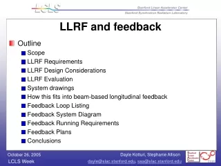
LLRF and Beam-based Longitudinal Feedback • Outline • Scope • Local feedback loop requirements • How this fits into global feedback • Other signals • Conclusions
Scope • The low level RF controls system consists of RF phase and amplitude controls at these locations: • Laser • Gun (Klystron 20-6) • L0-A, a.k.a. L0-1 (Klystron 20-7) • L0-B, a.k.a. L0-2 (Klystron 20-8) • L0 Transverse cavity (Klystron 20-5) • L1-S (Klystron 21-1) • L1-X (Klystron 21-2) • L2 - (Klystrons 24-1,24-2,24-3) to control avg phase/ampl of L2 • L3 Transverse cavity (Klystron 24-8) • L3 - 2 sectors of klystrons, S29+S30
Local feedback loop requirements • At each of these locations, the klystron’s phase and amplitude will be monitored and controlled • When beam is present, control will be done by beam-based longitudinal feedback (except for T-cavs); when beam is absent, control will be done by local phase and amplitude controller (PAC)
Conclusions • At 120 Hz, the LCLS LLRF raw signals must be processed, the phase and amplitude corrections must be sent out, applied and achieved • When there is beam, this system will integrate with the beam-based longitudinal feedback by accepting the latter’s RF phase and amplitude corrections and passing them on.