Download
1 / 26
260 likes | 381 Views
Forward Error Control Repair errors at receiver Eliminate retransmission Important in digital wireless communications. (i) Additional bits to detect corrupt bits ~ FCS with CRC (ii) Additional bits to locate corrupt bits (iii) Correct: Invert corrupt bits (for binary data).

E N D
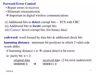
Forward Error Control • Repair errors at receiver • Eliminate retransmission • Important in digital wireless communications (i) Additional bits to detect corrupt bits ~ FCS with CRC (ii) Additional bits tolocatecorrupt bits (iii) Correct: Invert corrupt bits (for binary data) • codeword: word formed by data bits & additional check bits • hamming distance: minimum bit positions in which 2 valid code • words differ • if hamming distance = n cannot detect n bit errors • ie: parity bit: n = 2: • original datareceived data (2 bit error undetected) • 0000000 0 0000011 0
error detection & correction properties are related to hamming distance • Thm 1: to detect n bit errors required hamming distance = n+1 • Thm 2: tocorrect n bit errors required hamming distance = 2n +1 • ie: to detect 16 bit errors 17+ extra bits needed • to correct 16 bit errors 33+ extra bits needed
1. Hamming Single Bit Code(limited use for data transmission) • - simplest error correction scheme • - code detects & locates single bit errors • block code: original message is treated as a block during encoding & decoding • block ofk source bits encoded to produce n-bit block (n > k) • encoder produces (n,k) code • code rate or code efficiency = k/n • redundancy = 1- k/n • memoryless output depends only on current encoded k-bit • message * can detect but not locate 2 bit errors ** most communications errors are burst errors, useful for semiconductor memory
bit positions codeword • ie: 7 bit data field with 4 check bits (occupy 2n bit positions 1,2,4,8…) • (11,7) hamming code • code rate = 7/11 • redundancy = 1 – 7/11 • (1) sender derives check bits • Add 4 bit numbers corresponding to bit positions with ‘1’ using • modulo 2, no carry • 4 bit values correspond to check bit positions: 23, 22, 21,, 20 • (2) receiver recovers bits & checks • 4 bit binary number corresponding to bit positions with binary • 2 are added again • if no error sum = 0
(1) sender generates codeword: add bit positions with ‘1’ final codeword e.g. data = 1001101
(2) receiver checks data • check codeword: sum = 0 • if no error receiver has same result let bit 2 be corrupt sum is = 2
decimal binary 11 1011 8 4 2 1 11 10 9 7 6 5 3 10 1010 0 1 1 1 1 1 0 0 0 0 1 4 0100 3 0011 2 0010 sum= 0101 1 0001 e.g. data = 1100011 (1) sender generates codeword: add bit positions with ‘1’ final codeword (2) receiver checks data: let bit 5 be corrupt
2. Convolutional Codes (not memoryless) • continuous stream of source bits produce continuous stream of • encoded bits • sequence of source bits is convolved to produce output ‘symbols’ • each encoded bit depends on • - current bit input bit • - previous sequence of input bits • shift register used in practice length = constraint length • convolution operation performed using modulo 2 adders (XOR • gates)
Input Sequence 101011 Encoded Sequence 10 10 10 11 01 11 S1 S2 S3 • e.g. encoding with 3 bit shift register & 2 XOR gates • - convolutional encoder with constraint length = 3 • - for 1 input bit 2 output bits generated code efficiency = ½
Techniques for determining output sequence • 1. tree diagram • 2. state diagram • 3. trellis diagram (used for demonstrating decoding derive initial • outputs)
output bit pair placed on the outside of each branch line • register contents, S1, S2, S3 placed on the inside branch line • number of branches doubles for each input • repeats after 2nd branch level - only 4 unique branch nodes • only 4 States, irrespective of position in tree • same output pair • same new node state occurs • Tree Diagram: • Node = branch points • input bit = 0 take upper branch • input bit = 1 take lower branch
e.g. Tree Diagram O2O1 A A 00 00 01 11 10 010 011 000 000 001 00 B 000 110 101 111 100 100 C 10 11 01 11 00 B Next Input Bit = 0 D 0 0 0 A Next Input Bit = 1 S1S2S3 10 register state C 010 11 B 011 100 encoded output C 11 110 D D 01 S1 S2S3
Encoding input S ..S new output 1 3 node state 0 00 A 000 A 1 11 A 100 B 0 10 B 010 C 1 01 B 110 D 0 01 C 001 A 1 10 C 101 B 0 11 D 011 C 1 00 D 111 D
0 0 0 A A A A 00 11 11 00 10 01 11 00 10 10 00 01 01 011 001 000 010 000 010 000 010 001 011 001 000 011 B B B B 00 000 110 101 110 100 111 100 111 100 111 101 101 100 110 D C B A C C C C 00 01 01 11 11 10 00 11 10 10 11 01 00 input bit S1 S2 S3 output C D D D D C D D B B A A 1 100 11 1 110 01 0 011 11 10 1 101 10 010 0 010 10 100 11 110 01
Use tree diagram to define encoder states A,B,C,D • Draw trellis diagram to exploit repetitive nature of tree diagram • condensed representation of all possible encoder outputs from all • possible inputs • for specific input, single path through trellis and hence output • bits results
00 00 00 00 00 A A A A A A 11 11 11 11 11 B B B B B 10 10 10 01 01 01 input bit S1 S2 S3 output 01 01 01 01 1 001 11 C C C C 10 10 10 10 1 011 10 0 110 11 11 11 11 1 101 01 D D D D 0 010 01 00 00 00 e.g. initially assume registers cleared (000), input sequence = 11010…
Decoding: given an incoming bit stream with possible bit errors • determine most likely output sequence • assume receiver has knowledge of the encoder used at source • compare received sequence with possible encoder sequences • select closest match • Sequence Selection: • compute hamming distance of received sequence with all possible • sequences • compare against all possible sequences = all paths thru trellis • select sequence with the smallest hamming distance • requires comparison of entire incoming stream to all paths thru • trellis -impractical!
Viterbi algorithm – practical approach for path selection • maintain hamming distance between received sequence & sub-set • of possible sequences • at each node in the trellis – eliminate a path • - always 2 paths merging at each node retain only 1 survivor path) • - path selected is minimum hamming distance • - other path is terminated • - tie goes to upper path (lower path is eliminated)
final path: path thru trellis has the minimum aggregate hamming distance • maximum likelihood decoder: finds most likely path for received • sequence • No FEC can identify all errors • goal is to reduce corrupt packet retransmission • typical reduction BER with rate ½ convolution code 102..103 • used with ARQ error control fewer retransmissions & overall • efficiency improved
00 00 00 00 00 A A A A A A 11 11 11 11 11 B B B B B 10 10 10 01 01 01 01 01 01 01 C C C C 10 10 10 10 11 11 11 D D D D 00 00 00 input sequence = 10011… encoded output sequence = 11 01 10 11 10 00…
transmitted symbol stream assume received symbol stream 11 01 10 11 10 00 11 0100 11 11 00 – 2 bit errors symbol symbol previous symbol stream next hamming number state state distance 11 1 00 A 2 11 B 0 symbol symbol previous symbol stream next hamming number state state distance 01 2 00 00 A 2 + 1 = 3 00 11 B 2 + 1 = 3 11 01 C 0 + 0 =0 11 10 D 0 + 2 = 2
transmitted symbol stream assume received symbol stream 11 01 10 11 10 00 11 01 00 11 11 00 – 2 bit errors symbol symbol previous symbol next hamming number state stream state distance 3 00 start_selection 00 00 00 A 3 + 0 = 3 00 00 11 B 3 + 2 = 5 00 11 01 C 3 + 1 = 4 00 11 10 D 3 + 1 = 4 11 01 10 A 0 + 1 = 1 11 01 01 B 0 + 1 = 1 1 1 10 11 C 2 + 2 = 4 11 10 00 D 2 + 0 = 2
transmitted symbol stream assume received symbol stream 11 01 10 11 10 00 11 01 0011 11 00 – 2 bit errors symbol symbol previous symbol stream next hamming number state state distance 4 11 C 00 11 01 10 A 4 + 1 C 00 11 01 01 B 4 + 1 11 01 10 00 A 1 + 2 A A 11 01 10 11 B 1 + 0 B 11 01 01 01 C 1 + 1 11 01 01 10 D 1 + 1 B D 11 10 00 11 C 2 + 0 D 11 10 00 00 D 2 + 2
transmitted symbol stream assume received symbol stream 11 01 10 11 10 00 11 01 00 11 11 00 – 2 bit errors symbol symbol previous symbol stream next hamming number state state distance 11 5 A 11 01 10 00 00 A 3 +2 11 01 10 00 11 B 3 +0 A 11 01 10 11 01 C 1 +1 B 11 01 10 11 10 D 1 +1 B 11 01 01 01 10 A 2+1 C C 11 01 01 01 01 B 2 +1 D 11 01 01 10 11 C 2+ 0 D 11 01 01 10 00 D 2+ 2
transmitted symbol stream assume received symbol stream 11 01 10 11 10 00 11 01 00 11 1100– 2 bit errors symbol symbol previous symbol stream next hamming number state state distance 00 11 01 10 00 11 01 C 3 +1 6 B B 11 01 10 00 11 10 D 3 +1 11 01 10 11 01 10 A 2 +1 C C 11 01 10 11 01 01 B 2 +1 D 11 01 10 11 10 11 C 2 +2 D 11 01 10 11 10 00 D 2 +0 A 11 01 01 01 10 00 A 3+0 A 11 01 01 01 10 11 B 3+2 original data stream recovered with 2 bit errors out of 6 bits