Pneumatic Systems
Pneumatic Systems. Alex Zenanko TEC 366 Mr. Chris Marker. FLUID POWER: PNEUMATICS. I. What is Pneumatic?

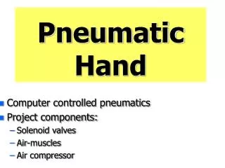
Pneumatic Systems
E N D
Presentation Transcript
Pneumatic Systems Alex Zenanko TEC 366 Mr. Chris Marker
FLUID POWER: PNEUMATICS I. What is Pneumatic? “A power transmission system that uses the force of flowing gases to transmit power” [ ToolingU.com] Word origin is Greek- “Pneuma” meaning “wind, breath” II. How big is the fluid power industry? U.S. $14 billion $40 billion worldwide Trivia: The first subway was pneumatically powered Chicago Postal service had miles of underground pneumatic tubes for mail delivery
EVOLUTION HISTORIC MODERN • Ancient Greece • Simple devices • Bellows used by blacksmiths • Otto Von Guericke • Revolutionized Air Compressors • More Power and Efficient • 1829 first compound air compressor patented • Characteristics of gases explored • Pneumatic hammer and tubes hit the market • Higher Pressure Used • Jet Engines • Electronic Control • Digital Logic Integration • Axial Flow Compressors • Highly complex Robotics • Standardization
Gases 101 Basic gas characteristics: A gas will take the shape of its container no matter the size Gases are highly compressible Gases exert a force on the walls of its’ container (can be measured/predicted) Gases have 3 interrelated properties 1. )Temperature 2.) Pressure 3.) Volume Boyles Law- describes the pressure and volume relationship of gases As volume decreases, pressure increases. (P1 x V1) = (P2 x V2) Combinational Gas Law = (Pictured Top Right) mathematical representation of the three interrelated properties. “If three conditions of a gas are known, then a change in any one of the conditions can be predicted if changed” P=pressure V=volume T=Temperature Kelvin R=Energy Constant
Instant Physics: Gases Terms Pressure- Perpendicular force per unit area. ** Force per unit area acts on surface area and not mass Absolute Pressure = [+/-] gauge pressure + atmospheric pressure This method uses atmospheric pressure as a reference level to scale from Pascal’s Law- A pressurized gas exerts an even force on the walls of container. F = P x A °F to °C: °C = (°F –32) / 1.8 °C °C to °F: °F = (°C x 1.8) + 32 1 H.P. = 4 cfm at 100 psi
Basic Pneumatic System A) Compressor Pressurizes Air Typically attached to tank for storage Often is a centralized supply for multiple devices B) Check Valve One way valve Prevents backflow into compressor Prevents compression loss when off C) Accumulator Smooth air flow and unwanted disturbances D) Directional Valve Direct Air flow Stores energy and reduce turbulence Electrical or manual operation E) Actuator Transfers air energy into motion Ex. Air Chisel
I. Compressors Are commonly powered by electric motors Must be matched for each application 1. Positive Displacement Compression Stroke creates pressure Most diverse field. 2.Dynamic Air velocity creates pressure -Imagine the energy and power of a river flowing down a mountain. This energy is transferred into pressure.
Positive Displacement Compressors Positive Displacement Divisions: Rotary & Reciprocating Lubrication--- “Wet or Dry” Reciprocating- 1-50 H.P. applications Piston/Cylinder/Valves Works Like Internal Combustion Engine 1.)Single, Double Acting and Multistage types available and describe how air is pumped Double Acting is most common in industry; 100 psi classification
Positive Displacement Compressors Rotary Rotary Screw- Excellent for continuous operation 100+ hp applications Two helical screws placed side by side compress air when one screw is turned Rotary Vane- Blades of different length mounted to center hub on drive shaft Length difference causes pressure pockets to be created when drive shaft turns Scroll- Two offset spiral disc placed on top of each other inside of circular housing The top disc remains fixed as the lower disc orbits around the housing walls This creates a seal and a vacuum that sucks air in chambers of varying size As the bottom disc orbits the chamber size is decreased and air becomes compressed
Axial Dynamic Compressors Centrifugal • Uses spinning impeller mounted to solid shaft increase air velocity . • Air is then channeled into a diffuser • Diffuser = gradually increases in size as gas leaves impeller • Spinning Airfoils compress air • Airfoils are arranged in fixed and moving rows along the compression chamber • Extremely Efficient; 90% is achievable
Advanced Components Lubricator Automatically lubricates system through air supply. Oil helps elastomeric seals and moving parts work Not all devices require lubrication: A coalescing filter removes oil Muffleraka “Silencer” Cancels out undesirable frequencies created by venting exhaust air through porous substance Coalescing mufflers = reduce sound and oil Air Booster Tank and Regulator Increases air pressure to certain parts of system Typically provide a small quantity of high pressure Work in-line with system after compressor Uses: Certain high demand machines; Peak times that exceed available pressure; 600 PSI To avoid cost of high performance compresor Ratio of inlet to outlet pressure change Ex.1/2 = Pressure is doubled [is listed in data sheet]
Advanced Components Aftercooler Dissipates heat created by compressing air Thermal expansion can limit the storage capabilities of a tank Pneumatic Logic Components Controls the flow of air through the system via controller, actuators and valves Very similar to PLC systems Is becoming more prevalent with advances in computing and increased machine complexity Coalescing Filters Absorbs oil added to air supply Is necessary for a system whose components will be damaged by oil It is required by OSHA to use a coalescing filter before exhausting air that has been oiled Piping Friction losses in piping can result in pressure loss Compressor must be separated from piping with flexible couplings to block system vibration Ring Lines are those which run in a large loop and feed machines along the loop Branch lines are the shorter lines that feed machines and other devices
Piping in Pneumatics Installation Must use flexible coupling to between compressor and piping. (Vibration) Piping must sl0pe downward away from compressor at 1-2 degrees [0.12-0.25 in/ft] Use Excess Flow Valve every 100ft Pressure Drop Inevitably effects all pneumatic systems Friction and piping length A 10% drop in pressure is the absolute maximum • Branch lines are the shorter lines that feed machines and other devices • Ring Lines are those which run in a large loop and feed machines along the loop
Pneumatic Dryer Removes moisture from air. Typically found after Coalescing Filter and/or FRL Dew point suppression = A temperature based scale that compares change in dew point value before entering the dryer and after leaving the dryer Question: Air enters a deliquescent dryer at 100 ° F and the dew point suppression is -1.5° F. What is the resulting dew point of the air? ***Moisture within the air will not condense if air temp. stays above 75° F Deliquescent Dryers = Absorption; [ 25° F] D.P.S Air is channeled through salt bed that traps both liquid and vapor Must be drained regularly. Typically element is in brick or tablet form Desiccant Dryers = Adsorption ; [ -40° F] D.P.S Moisture is absorbed on surface area of water absorbing substance. Typically silica gel or activated alumina is used. “Regenerative Dryer” = a process removes moisture so dryer can be used again Refrigeration Dryer = [ -40° F] D.P.S Industry favorite for a wide range of application due to cheap operating cost Removes moisture by cooling air to the point of condensation. Reheats afterwards Reduces need for heat sink on compressor up to 60%
Pneumatic Cylinders Type of Actuator that does work in the form of linear motion Can be thought of as the pneumatic muscle Types: Single Acting, Double Acting, and Double End Rod Single Acting- Single Pressure Port Can only be controlled in one direction A spring or load weight must reverse the cylinder’s movement Double Acting Two Pressure Ports Extension and Retraction can be controlled Double End Rod Two rods and Two Pressure Ports; Force is equal for each rod Area = πr2 Find the Area of a ¾” x 1 ¼” cylinder Area = 3.14 x (3/8”)2 Area = 3.14 x .14 Area = .44 in2 Force = Pressure x Area What is the force @ 10 psi
Cylinders Single Acting Spring ReturnDouble Acting
Pneumatic Logic Circuits Logic circuits are made from various valves Functional equivalent to logic gates Used to control sequence of events NOT, OR, AND, AND--All inputs must be active OR--If any input is active the output will be NOT--The output is the opposite of the input NOR and NAND are combinations of the basic gates
ANDORNOT -Or Valve- Output activated if A or B is activated -And Valve- Output activated only if A and B are high -NOT Valve- Output is opposite of input
Valves Sequence Valve Control sequence of operation between two branches of a circuit. A set pressure point will divert flow when reached Shuttle Valve Isolates two supply systems from each other. This valve supplies an output from one of two inputs that are kept isolated from each other Excess Flow Valve Safety Device. Cuts off flow if pipe breaks Pressure Control Valve Reduce and maintains lower pressure supply to output device. Is resistive to pressure changes on the supply side Limit Valve Field device used to generate and send control logic signal to processor. -It is active when event has occurred Ball Stop Valve Quick Acting valve; manual turn operation Gate Valve An adjustable wedge impedes the flow of air Must be rated if used to control pressure
Control Valve Symbology 2 Position 5 way: 5/2 Goal: Determine function of control valve 1) Ports/Way 1) Vertical Arrow = Flow Path 2) 45 deg Arrow = Exhaust Path Tee = Closed Path Numbering: 1 is always pressure port All odd’s > 1 are exhaust ports Even #’s are outlet ports (A & B are also used) 2)Position Envelope Indicate discrete # of flow paths. A Box surrounds a P.E. Depicts each setting and change ^Position 1^ Closed ^Position 2^ Open
5 port/2 way valve Left = Figure 1 : Right = Figure 2 Figure 1 Figure 2
Pneumatics Symbols 1.)FRL[Filter/Regulator/Lubricator] 2.) Single Acting Cylinder3.) Double Acting Cylinder ------------------------------------------------------------------------------------------------------- 1.)FRL[Filter/Regulator/Lubricator] 2.) Single Acting Cylinder3.) Double Acting Cylinder
Formulas 1. Pressure Dropsid=[Receiver Pressurepsig– Tool Pressurepsig / Line Distanceft PSID = (RP – TP) / D 2. Compression Ratio = (Pressurepsig+ 14.7) / 14.7 CR = (PSIG + 14.7) / 14.7 3. Air Leakage Cost$/min = Flowcfmx Timemin x Electricity UsedkWh/cu-ft x Electricity Cost$/kWh Leakage Cost$= cu-ft xmin x (kWh/cu-ft) x ($/kWh) 4. Absolute Pressurepsia= Gauge Pressurepsig+ 14.7 5. Forcelbs = Pressurepsig x Areasq-in P = F x A
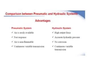
Pneumatic vs. Hydraulics Pneumatics Hydraulics • Use gases • Gases are easily compressed • Good power density • Lower Pressures • Quicker • Use liquids • Liquids compress only slightly • Better power density • Higher Pressures • Slower
Pneumatic vs. Hydraulics: Pneumatics Hydraulics • Air is abundant and free • Less environmental concerns • Lower initial cost • Higher operating cost • Design Simplicity • Lower maintenance • Must purchase fluids • Leaks can harm environment • Higher initial cost • Lower operation cost • Complex Design • Very high maintenance
Lab 1 Overview: Flow Measurement Measuring fluid flow in pneumatic systems is far more difficult than in hydraulics systems Direct measurement in pneumatic systems can be very inconvenient however it is more accurate Indirect methods are convenient but sacrifice accuracy Ex. rotameters, orifice meteres, pitot tubes. In this lab we will be using a rotameter Measurement: Industrial standard is cubic feet per minute ‘cfm’ for large flow and cubic feet per hour ‘cfh’ for small flow Corrections must be made using mfg. supplied table
In this lab we will be using: • Dwyer RMA series Rate-master Rotameter(100psi) • Vega model 200 Pneumatic System • 5/32” Pneumatic tubing (12” length) • When connecting tubing to the flowmeter • Eliminate or minimize sharp bends and flow restrictions when possible • Testing Procedure: • Mount the flowmeter vertically • Connect red hose from compressor manifold to bottom inlet of the flowmeter • Make sure manifold needle valves are shut • Turn on compressor • Adjust regulator to 20 psi • Open needle valve slowly two full turns • Record measurement when ball is stabalized • Repeat for 30 and 40 psi 9. Find actual airflow using correction chart • asdf
Lab 2 & 3. Air Leaks and Cylinders • Air Leaks cost money. Air leaks are going to happen eventually . • How to evaluate the cost of leaks is the goal of this lab. 1.) Use the CFM measurements from Lab 1 2.) Use$.58 cents/ kWh as Al industrial rate avg 3.) Assume the motor consumes $.02 kWh/cu-ft 4.) Assume the system runs 24 hours a day 5.) Apply the air leakage cost formula Leakage Cost$= cu-ft xmin x (kWh/cu-ft) x ($/kWh) a
Lab 4. Conveyor The goal of this lab is to determine the air line configuration for the conveyor
Lab 3. Conveyor The goal of this lab is to determine the air line configuration for the conveyor