Download
1 / 58
580 likes | 868 Views
What information do you need? What kinds of data would you expect to have?. Gravity Water Supply Design. Gravity Water Supply Design. Design flows Population projection Demand variability Tank buffering Transmission line design algorithms Air in pipelines. Population Projection.

E N D
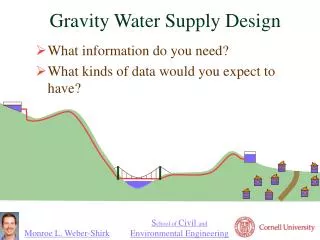
What information do you need? • What kinds of data would you expect to have? Gravity Water Supply Design
Gravity Water Supply Design • Design flows • Population projection • Demand variability • Tank buffering • Transmission line design algorithms • Air in pipelines
Population Projection • Example from Agua Para el Pueblo (Honduras) • Count the houses • Assume 6 people per house • Assume linear growth for design period • N = design period • K = growth rate
Water Demand • Assume a per capita demand (this might be based on a governmental regulation) • Multiply per capita demand by the future population to get design average demand • Multiply average demand by peak factors to get maximum day demand and maximum hour demand
Peak Flow Factors Dt range typical value day 1.5 - 3.0 1.8 hour 2.0 - 4.0 3.25 Running average over time Dt “In small water systems, demand factors may be significantly higher than those shown…” C Chin. Water-Resources Engineering
Peak Flow Factors (2) • A dimensionless quantity • What is it a function of? • __________________ • Longest interval _____ • Shortest interval _____ • __________________ Averaging interval year ? Number of taps (Population) 1 day Where is steep slope?______
Population and Peak Flow Factor • What is the instantaneous peak factor for one person? • Average flow (100 l/d) • Max flow (5 l/min = 7200 l/d) • What is the maximum (typical) duration of this high flowrate? • 20 minutes would get average daily flow so perhaps this is a reasonable guess (1200 s) 7200 72 100
Peak factors and Transmission Lines • The smallest diameter transmission line that could possible work is one that would exactly provide the average demand • We would need to accommodate the variable demand with a very large storage tank (that could handle seasonal fluctuations)
Tank size – Pipe diameter tradeoff • The peak factor is small for time periods greater than 1 day • The storage volume required for long time periods is great • Tanks are typically designed to accommodate fluctuations over periods of time less than one day • Transmission lines are designed to accommodate flow for the maximum day • If the transmission line has a length of zero meters, what size should the distribution tank be? Eliminate the tank???
Distribution Storage Tank Functions • Buffers demand fluctuations • Chlorine contact time for disinfection • Can be used during transmission line maintenance operations to provide continuous supply • If transmission line fails the system continues to provide water • Fire protection • Which function dominates?
Design Flows • Transmission Line Design flow • Based on maximum daily demand at the end of the system design life • Distribution system design flows • Take maximum hourly flow at the end of the system design life • Divide that flow by the current number of houses to get a flow per house • The flow in each pipe is calculated based on the number of houses downstream • This flow scheme doesn’t work for small systems!!!! Tank provides buffering for 1 day
Pipe Diameters • How are pipe sizes chosen? • Energy Equation • An equation for head loss • Requirement of minimum pressure in the system • Pipes must also withstand maximum pressure V is typically less than 3 m/s for pipelines
EGL Distribution Tank HGL Spring box Air release valves Transmission Line Design
Hydraulic Grade Line Minimum • Avoid having the HGL below the point in the system for which it is plotted (negative pressure) • Air will accumulate at intermediate high points in the pipeline and the air release valve won’t be able to discharge the air if the pressure is negative
Air Release Valves • Air release valves are prone to failure • Must be located precisely • I hope to provide more info in section on air in pipes http://www.ipexinc.com/industrial/airreleasevalves.html http://www.apcovalves.com/airvalve.htm
Critical point Transmission Line Design • Where do we get each term in the equation for pipe diameter? • What is wrong with the slope of my lines?
Transmission Line Design Steps • Calculate the ratio for each known point along transmission line starting from the source. • L is the total pipe length (not horizontal distance) • Find the maximum ratio • Find the minimum pipe size
Transmission Line Design Steps Continued • Round up to the next real pipe size (check your materials database) • Calculate the location of the HGL given the real pipe size • Calculate the location of the HGL at critical point i • Now begin at point i at the HGL elevation and repeat the analysis
Designing the next section We are finding the HGL that meets the requirement “HGL must be above the pipeline” Actual HGL given real pipe size Pipelines can have multiple critical points or a single critical point (the end of the line!)
Alternate Pipe Size Selection Procedure • Given design flow rate, calculate for each pipe • Given the required ratio of pipe length to elevation drop select a pipe from the appropriate schedule that has a value of that is greater than the required value
Mix pipe sizes to get design flow • We could mix a large pipe and a small pipe to more closely deliver the design flow • Given total pipeline length (L) and total elevation difference (hf) • Select a pipe with smaller (L/hf)1 and a pipe with larger (L/hf)2 • Calculate length of each pipe required subject to total length and total head loss constraints
Two Pipe Size Mix Head loss constraint Length constraint
Mixing pipe sizes • If you install the small pipe upstream from the large pipe it is possible that the HGL will drop below the pipeline • If there aren’t any other constraints, install the large pipe diameter upstream • If possible, use the small pipe where higher pressure rating PVC or galvanized iron pipe is required
Pressure Constraints • Different “schedules” of pipe can withstand different pressures (higher pressure means thicker walls means more money) • The system must be designed so that a valve can be closed right at the distribution tank and the pipes must withstand the resulting static pressure (p=rgh)
Different pipe materials • Galvanized iron pipe is more expensive than PVC and is rougher (has more head loss) • So it can be logical to use smaller galvanized iron pipe than PVC pipe even though the head loss will be much greater through the iron pipe!
Goal is to get design flow rate at minimum cost • I am not sure what the correct algorithm is! • The available energy can be “spent” as head loss wherever you like • Goal is to use the energy where it reduces the project cost most • Use smaller diameter pipes for high pressure sections of PVC pipe or for galvanized iron pipe • Head loss changes rapidly as pipe size changes, so it will only be possible to use slightly smaller pipes.
Hydraulic Gradeline 1.5” 2” HGL Static HGL 112 m
Pressure Break • A small tank (with a free surface) in a pipeline used to prevent high pressure downstream from the pressure break • Inflow can be regulated by a float valve • If inflow is unregulated excess water will exit through an overflow • Pressure breaks can be installed to make it possible to use cheaper pipes
Surveying Vertical angle q Dx r Dz
Surveying using Stadia Vertical angle q Dx r Dz c b The reading is on a vertical rod, so it needs to be corrected to the smaller distance measured perpendicular to a straight line connecting the theodolite to the rod. a
Horizontal Distance Trig identity M is the Stadia multiplier (often 100) c is the Stadia reading
Vertical Distance Trig identities
GPS surveying accuracy • 100 meters: Accuracy of the original GPS system, which was subject to accuracy degradation under the government-imposed Selective Availability (SA) program. • 15 meters: Typical GPS position accuracy without SA. • 3-5 meters: Typical differential GPS (DGPS) position accuracy. • < 3 meters: Typical WAAS position accuracy • WAAS not available everywhere
GPS with Barometric Altimeter • 15 m isn’t nearly good enough for vertical measurements when designing pipelines • Barometric pressure decreases with elevation • Can we use barometric pressure to measure elevation? We need an accurate measure of______
Perfect Gas at Constant Temperature (Isothermal) r is function of p Mgas is molecular mass Integrate…
Perfect Gas with Constant Temperature Gradient • The atmosphere can be modeled as having a constant temperature gradient Lapse rate b = 0.00650 K/m Mt. Everest 8,850 m
Pressure Differential • To measure a 1 meter difference in elevation the altimeter must be able to resolve a 10 Pa difference in pressure given a total pressure of approximately 100,000 Pa • Barometric altimeters require extremely high resolution (5 or 6 digits of precision)
Elevations that are as Changeable as the Weather • Changes in the weather can produce barometric pressure differences of 2500 Pa • This pressure change translate to an elevation error of 220 m! • Compensation for barometric pressure fluctuations is essential • Use a 2nd barometric altimeter to log elevation while at a fixed location
Air in Pipelines • Three sources of air • Startup • Low flow • Air super saturation
Air Outline • Will the water flow with air in the pipeline? • HGL for a pipeline with air • Trapped air volumes • Dimensional Analysis? • Under what conditions will the air be forced through the pipeline? • Air handling strategies • Air release valve at all high points • Conventional strategy • Valves must be placed carefully • Design high flow rates that carry air downstream
Will water flow in the pipeline? Constant pressure • What is the slope of the HGL in the section of pipe with air? ___________________ • How much head is lost in the air section?______ • What does the HGL look like if a valve is closed at the end of the pipeline? • How much head is available for major losses? Same as slope of pipeline height
What is the volume of air? • Function of • Topography • Air entrapped during filling • Air carried in during operation • Worst case • All downward sloping pipe downstream of a high point (other than the source) could be filled with air
Air purge: length, velocity, density, forces • Length: • Velocity: average water velocity • Density: • Forces: pipe diameter, pipe length, elevation change water density, air density inertia, viscosity, gravity, surface tension Will there be a transition in water surface elevation? Froude number!
What mechanism moves the air? • Shear between water and air • Entrainment of air by turbulence • Hydraulic jump at the bottom of the air column • Waves and whitecaps down the incline • As the flow rate increases, is there a transition when it is no longer possible for the water to switch to open channel flow?
Air Entrainment by surface breakup beAir Entrainment (perhaps fraction of fluid that is air) But according toGilles Corcos the entire “sock” of air is carried through the system at once. Another mechanism moves the water out before shear gets this large! Is the air pulled out or pushed out?
Subcritical vs. Supercritical • The energy grade line must always drop in the direction of flow • If the flow switches from full pipe to partial pipe the velocity must increase as the depth decreases ______________ • At a certain critical velocity it is no longer possible to reduce the depth because it would require a net increase in energy ___________________________________ K.E. increases Froude number K.E. increase > P.E. decrease
Waves… • Another way to think of this… • The air is forced out of the pipeline by a wave that is traveling down the pipe • The wave is forced to travel down the pipe when the wave speed is less than the water velocity! • Froude number is the ratio of the water velocity to the wave speed! Mach is pressure wave speed, Froude is gravity wave speed
r y A T Wave propagation c is wave velocity relative to water The wave speed is not a function of the air pressure! y is the water depth… … water depth in a pipe Better definition