Download
1 / 22
220 likes | 360 Views
Dirty RF Impact on Interference Alignment. Per Zetterberg. Outline. Goal Approach Interference-alignment and CoMP Implementation Results Impairment-modeling ( closening the gap theory-simulation) Conclusion. Goal. New interesting and challenging techniques.

E N D
Dirty RF Impact on Interference Alignment Per Zetterberg
Outline • Goal • Approach • Interference-alignment and CoMP • Implementation • Results • Impairment-modeling (closening the gap theory-simulation) • Conclusion
Goal New interesting and challenging techniques Assumption: Results are general. Robust approaches FER EVM SINR Match! Impairment- modeling Detailed simulation Testbed Measurements (USRP) Channels
Approach Impairment- modeling Basic simulation Test-bed Measurements (USRP) Impairment model Spectrum analyzer Transmitter PC
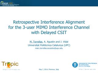
Interference alignment Cadambe/Jafar, ”Interference Alignment and Degrees of Freedom of the K-User Interference Channel”, IEEE Trans, Information Theory 2008. K-transmitters and K-receivers, K-links: K/2 simultaneous interference-free links. Requires coding over multiple channel realizations. Global channel knowledge required.
Interference-alignment incarnations In frequency-domain: Something new –will be studied later. In antenna-domain: Co-ordinated beam-forming.
Implementation IA Feedback: Wired ethernet MS 1 BS 1 BS 2 MS 2 MS 3 BS 3
Implementation: CoMP Feedback: Wired ethernet MS 1 BS 1 BS 2 MS 2 MS 3 BS 3
Beamformer Formulate virtual uplink SINR. Iterate “Approaching the Capacity of Wireless Networks through Distributed Interference Alignment", by Krishna Gomadam, Viveck R. Cadambe and Syed A. Jafar.
Frames Demodulation reference signals CSI reference signals Payload 10 OFDM symbols Payload 10 OFDM symbols • MS feed-back CSI to BS1. • BS1 calculate beam-formers. • BS1 sends weights to BS2, BS3. • BS1-BS3 frequency locked. 38 subcarriers, 312.5kHz carrier-spacing QPSK, …., 256QAM 0.25, 0.5, 0.75 –rate LDPC codes
Preliminary Results 16QAM, 0.75 rate coded. 432 frames transmitted.
Power-Amplifier Non-linearity OFDM signals: n + y+n(t) Modeled as noise: D Dardari, V. Tralli, A Vaccari “A theoretical characterization of nonlinear distortion effects in OFDM systems“, IEEE Trans. Comm., Oct 2000.
MIMO case Correlation ? OFDM signals: n + (t) OFDM signals: n + (t)
Phase-noise Modeled as additive noise + CPE BPF LNA LPF A/D CPE: Slowly varying between symbols y(t) R. Corvaja, E. Costa, and S. Pupolin, “M-QAM-OFDM system performance in the presence of a nonlinear amplifier and phase noise, IEEE Trans. Comm. 2002.
CoMP Results Without impairment model With impairment model
IA Results Without impairment model With impairment model
Conclusion: What will be answered? • How much worse is IA practice than in theory? • What practical impairments need to be modeled? • (==> can lead to improved robust designs) • Is IA still worthwhile with impairments compared to base-lines ? Other outputs • Software environments that can be re-used (commodity hardware) • Increased understanding of software and hardware issues and implementations in our research community and our PhDs in particular. • Course-work for the above.
Structure of model TX TX Channel TX- impairment RX RX RX TX
Our Hardware GPS PPS, 10MHz USRP N210 Sample-rate: 100MHz Streaming: 25MHz Gbit-Ethernet PC Linux We have 18 USRPs
The 4Multi Software FrameWork (Multi-Antenna, Multi-User, Multi-Cell, Multi-Band) • Send data in small bursts (relaxes computational load) • Nodes synchronized by external trigering (PPS) • The implementor (basically) only need to program three functions node::init, node::process and node::end_of_run. • Simulate the system using “simulate” generic function. • Everything that can be compiled with gcc can run (e.g IT++) • Toolbox with coding&modulation. • Store _all_ received signals for post-processing. • Vision: • “The coding should be as easy as performing ordinary • (but detailed) desktop simulations”