Download
1 / 13
130 likes | 290 Views
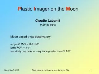
P lastic I mager on the M oon. Claudio Labanti IASF Bologna. Moon based g -ray observatory: range 50 MeV – 200 GeV large FOV ( ~ 3 sr) sensitivity one order of magnitude greater than GLAST. Gamma ray experiments history. SAS-2 (1972 - 1973) 20 MeV – 1 GeV spark-chamber

E N D
Plastic Imager on the Moon Claudio Labanti IASF Bologna Moon based g-ray observatory: range 50 MeV – 200 GeV large FOV (~ 3 sr) sensitivity one order of magnitude greater than GLAST
Gamma ray experiments history SAS-2 (1972 - 1973) 20 MeV – 1 GeV spark-chamber COS-B (1975 - 1982) 30 MeV – 3 GeV spark-chamber 50 cm2 EGRET (1991 - 2000) 100 MeV – 30 GeV spark-chamber ~1000 cm2 AGILE23.4.2007 - 30 MeV – 50 GeV Si-tracker & MCAL ~1000 cm2 GLAST (~2007 - 30 MeV – 50 GeV Si-tracker & CAL ~8000 cm2
Gamma ray Science • Galactic topics (SuperNova Remnants, Pulsars, Unidentified AGILE and GLAST sources). To understand the mechanisms of particle acceleration in Pulsars, and SNRs. • Detailed study of the spectral phase variations of Pulsar emission will be used to determine the physics of the particle accelerator associated with these objects. • Study of the dynamics of shocks in SNRs. • Constraining the contribution of unidentified sources to the diffuse emission from the Milky Way. Through observations of diffuse gamma-ray emission produced by interactions of Cosmic-Rays with interstellar gas and photons it could be possible to verify the actual models describing CRs as accelerated in the shocks of SNR. • The detection in the Milky Way of a broad spectral feature centered at 68 MeV signaling the decay of neutral pion, has escape detection so far. This feature can be searched next to SNR.
Gamma ray Science • Extragalactic topics (Active Galactic Nuclei, Gamma Ray Bursts). • Gamma-ray observations of AGNs will probe supermassive black holes through jet formation and evolution studies, and provide constraints on the star-formation rate at early epochs through photon-photon absorption over extragalactic distances. • Understanding the particle acceleration in AGNs and the formation of jets. • Determine the high-energy behavior of Gamma-Ray Bursts. • Study of the extragalactic diffuse background. Isotropic diffuse gamma-ray flux above 30 MeV has been observed. It can be interpreted either as the superposition of faint point sources or as the relic radiation from some high energy process in the early Universe, such as neutralino decay. The test of the models will require removal of the contribution from the resolved point sources and of the foreground Galactic flux. • Fundamental physics (Dark Matter, Test of Quantum gravity models with other lower energy instruments). • Observing monoenergetic gamma-ray "lines" above 30 GeV from super-symmetric dark matter interaction; detecting decays of relics from the very early Universe, (cosmic strings or evaporating primordial black holes). • Using GRB to detect quantum gravity effects.
Tracker telescope concept g -rays passing through an Anticoincidence shield (sensitive to charge particles) interacts with a moderator, producing electrons and positrons. The trajectories of these particles are determined in a stack of position sensitive detectors (Tracker); a Calorimeter will measure their energies. courtesy AGILE team
2200 mm detection area TRACKER ASSEMBLY 1200 mm CALORIMETER ASSEMBLY 3500 mm ANTENNA radiator solar array 3600 mm North/South direction Equator line PIM concept courtesy AAS-I LABEN
X Tungsten plate Y Photodiode array with its connector Tracker assembly • Each layer is composed by: • two layers of parallel scintillator fibers, 1 mm thick (TBD), placed at 90°, (2000 fibers for both directions X and Y). • a tungsten plate 0.3 mm thick (TBD) on top of the fiber layers • a 10 mm (TBD) CFRP honeycomb panel acting as structural element • Layers distance: 50 mm (TBD) Top cover panel 20 L A Y E R S Photodiodes electronics connector side External frame layers Bottom panel Each scintillanting fiber will deliver at the photodetector a ‘digital’ signal when passed by a MIP particle. There is no need of a linear amplifying photodetector. courtesy AAS-I LABEN
PIM basic technology Scintillating fibers: Core material: Polystyrene Multi-Clad Fibers (thickness: 2% of fiber size) Trapping efficiency, square fibers: >7 % No. of H atoms per cc (core): 4.82 x 10²² Radiation length: 40 - 100 cm from: http://www.detectors.saint-gobain.com/ Light output for a MIP: > 50 ph @ 20 cm from photodetector in a 0.75 mm square fiber K. Rielage et. al: “The FiberGLAST detector…” Proc. 26th ICRC Conference, 5, 152, 1999
PIM basic technology Photodetectors for fiber readout: Si-PMT or Single Photon Avalanche Diode (SPAD) SPAD operated at voltage biases above the breakdown voltage (Geiger mode) so that a single incident photon give rise to a macroscopic current pulse. The avalanche process is then stopped by a current quenching circuit Technology status @ today: Dimensions from 20 to 200 mm Ø Q E @ 550 nm 48 % Output pulse rise and fall time < 2ns on 10 pF load Output pulse duration 20 ns Dead time 65 ns Dark counts @ 20 °C <250 (20 mm Ø), < 20.000 (100 mm Ø) @ 0 °C < 25 (20 mm Ø), < 500 (100 mm Ø) from: http://www.micro-photon-device.com/ 2 SPAD, one at each end of a fiber, will be used for read-out. A coincidence logic on the 2 SPAD signals will eliminate the dark counts of the photodetectors. Micro lenses will focus the light from the fiber into the SPAD
Calorimeter assembly Calorimeter concept: The particles detected on the tracker loose their energy on interacting with the regolite powder extracted from the Moon surface that fills the Calorimeter structure. The EM shower shape and the number of its particles is measured by layers of plastic scintillator with PMT read-out The calorimeter is composed by three layers of plastic scintillator sheets, laying on a CFRP honeycomb structural panel 25 mm thick on the top (TBD), 40 mm thick on the bottom. Each plane is composed by four sectors attached to the main structure frame. Each sector has two phototubes on each side (for a total of 16 phototubes per each layer). courtesy AAS-I LABEN
4 5 6 4 3 1 2 Regolite Loading Unit 1. Storing device • Pressurization device • Compressor 4. Pressurized inlet circuit 5. Filters 6. Pressurized outlet circuit courtesy AAS-I LABEN
PIM at a glance g -ray observatory Range 50 MeV – 200 GeV FoV ~ 3 sr Sensitivity 1.0 x 10⁻¹⁰ photons cm-2 s-1 (3 s, at E > 100 MeV) source detection for 107 sec. observation time Angular resolution some arc second @ 1 GeV Energy resolution > 10% (1 s) Time resolution some tenth of nsec Measurements continuous Site Equatorial belt. Moon side facing the Earth to ease communications Operating temp. -30 to +50 °C Moderate temperature control on the SPAD detectors Size ~ 3 x 3 x 3 m Mass ~ 4300 kg Power ~ 500 W Technology objectives - a particle Tracker based on scintillating fibre - tracker read-out system based on Single Photon Avalanche Diodes (SPAD) • calorimeter for high energy particles build with material collected on the Moon surface and plastic scintillators detectors Technology status: mature Science objective - Galactic diffuse emission. - Galactic sources (SNR, Pulsars, Unidentified sources). - Extragalactic sources (AGN, GRB). - Fundamental physics (Quantum gravity models, Dark matter)