Download
1 / 26
260 likes | 369 Views
Explore advanced proton driver systems for Neutrino Factory applications, focusing on power, energy, bunch length, and rep rate requirements. Study upgrade scenarios, linac enhancements, and accelerator optimizations.

E N D
NufactRAL and CERN p-drivers S. Gilardoni – CERN Based on contributions from:J. Thomason, ISIS Accelerator Division M. Aiba, E. Benedetto, R. Garoby and M. Meddahi, CERN
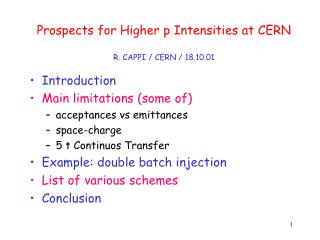
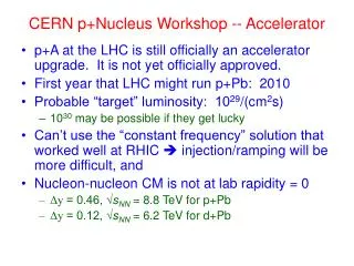
Multi-MW p-driver • Basic requirements: • 4 MW power on target • Energy between 5 – 15 GeV • RMS bunch length 1 – 3 ns • 50 Hz rep. rate. • 3 bunches, spaced by more than 80 μs
Proton Driver for a Neutrino Factory Chris Prior, Grahame Rees, Shinji Machida ( ) • Lower injection energies provide smaller • bucket area in the ring and the • small longitudinal emittance • needed for final ns bunch • compression. Studies • show that 180 MeV is a • realistic energy for NF • Separate main ring with optics chosen • for ns bunch compression. Could • be FFAG (cheaper but • insufficiently developed) or • a synchrotron (reliable, • tried and tested) • Special achromat for • collimation (longitudinal • and transverse) and • momentum ramping for • injection • Compressed • bunches need to be held and sent to • target at intervals of ~100 μs. Possible in FFAG and also synchrotron with flat top • Separate booster ring • designed for low loss phase • space painting for beam injection • and accumulation. Synchrotron moving • buckets give flexibility to capture all of the • injected beam 10 GeV RCS
ISIS Upgrades • Present operations for two target stations • Operational Intensities: 220 – 230 μA (185 kW) • Experimental Intensities of 31013 ppp (equiv. 240 μA) • DHRF operating well: High Intensity & Low Loss • Now looking at overall high intensity optimisation • Study ISIS upgrade scenarios 0) Linac and TS1 refurbishment 1) Linac upgrade leading to ~0.5 MW operations on TS1 Overlap with NF proton driver 2) ~3.3 GeV booster synchrotron: MW Target 3) 800 MeV direct injections to booster synchrotron: 2 – 5 MW Target 4) Upgrade 3) + long pulse mode option
ISIS MW Upgrade Scenarios 1) Replace ISIS linac with a new ≈ 180 MeV linac (≈ 0.5MW) 2) Based on a ≈ 3.3 GeV RCS fed by bucket-to-bucket transfer from ISIS 800 MeV synchrotron (1MW, perhaps more) 3) RCS design also accommodates multi-turn charge exchange injection to facilitate a further upgrade path where the RCS is fed directly from an 800 MeV linac (2 – 5 MW)
ISIS MW Upgrade Scenarios 1) Replace ISIS linac with a new ≈ 180 MeV linac (≈ 0.5MW) 2) Based on a ≈ 3.3 GeV RCS fed by bucket-to-bucket transfer from ISIS 800 MeV synchrotron (1MW, perhaps more) 3) RCS design also accommodates multi-turn charge exchange injection to facilitate a further upgrade path where the RCS is fed directly from an 800 MeV linac (2 – 5 MW)
ISIS MW Upgrade Scenarios 1) Replace ISIS linac with a new ≈ 180 MeV linac (≈ 0.5MW) 2) Based on a ≈ 3.3 GeV RCS fed by bucket-to-bucket transfer from ISIS 800 MeV synchrotron (1MW, perhaps more) 3) RCS design also accommodates multi-turn charge exchange injection to facilitate a further upgrade path where the RCS is fed directly from an 800 MeV linac (2 – 5 MW)
800 MeV, Hˉ Linac Design Parameters Grahame Rees, Ciprian Plostinar ( )
Common Proton Driver for theNeutron Source and the Neutrino Factory • Based on MW ISIS upgrade • with 800MeV Linac and 3.2 • (≈ 3.3) GeV RCS • Assumes a sharing of the beam • power at 3.2 GeV between the • two facilities • Both facilities can have the • same ion source, RFQ, chopper, • linac, H− injection, accumulation • and acceleration to 3.2 GeV • Requires additional • RCS machine in • order to meet • thepower • and energy • needs of the • Neutrino Factory • Options for the bunch compression to 1 – 3 ns RMS bunch length: • - adiabatic compression in the RCS • - ‘fast phase rotation’ in the RCS • - ‘fast phase rotation’ in a dedicated compressor ring
Preliminary design of the second RCS Jaroslaw Pasternak, Leo Jenner ( , , ) Parameters of 3.2 – 9.6 GeV RCS • Present-day, cost-effective RCS technology • Only three quadrupole families • Allows a flexible choice of gamma transition • Up to 3.7 MV/turn?
SPL-Based NFProton Driver Nearly GreenFieldSolution
LP-SPL: Low Power-Superconducting Proton Linac (4 GeV) Proton flux / Beam power Back-up LIU (2019) Present Main requirements of PS2 on its injector: 50 MeV Linac2 Linac4 Linac4 160 MeV HP-SPL: Upgrade of infrastructure (cooling water, electricity, cryogenics etc.) Replacement of klystron power supplies Addition of 5 high bcryomodules to accelerate up to 5 GeV 1.4 GeV PSB LP-SPL 2.0 GeV PSB 4 GeV PS PS 26 GeV PS2 50 GeV Output energy SPS 450 GeV LHC / sLHC 7 TeV
SPL-Based Proton Driver: Principle Accumulation of beam from the High Power SPL in a fixed energy Accumulator (5 GeV, 4MW beam power). Bunch compression («rotation») in a separate Compressor ring
SPL front end (Linac4): block diagram Linac4: 80 m, 18 klystrons 45keV 3MeV 3MeV 50MeV 94MeV 160MeV H- RFQ CHOPPER DTL CCDTL PIMS RF volume source (DESY) 45 kV Extrac. Radio Frequency Quadrupole 3 m 1 Klystron 550 kW Chopper & Bunchers 3.6 m 11 EMquad 3 cavities Drift Tube Linac 18.7 m 3 tanks 3 klystrons 4.7 MW 111 PMQs Cell-Coupled Drift Tube Linac 25 m 21 tanks 7 klystrons 7 MW 21 EMQuads Pi-Mode Structure 22 m 12 tanks 8 klystrons ~12 MW 12 EMQuads Ion current: 40 mA (avg.), 65 mA (peak) RF accelerating structures: 4 types (RFQ, DTL, CCDTL, PIMS) Frequency: 352.2 MHz Duty cycle: 0.1% phase 1 (Linac4), 3-4% phase 2 (SPL), (design: 10%)
Linac4 building Oct 2010 Linac4 Mar 2011 First user
HP-SPL: Main Characteristics Required for low loss in accumulator Ion species H− Output Energy 5 GeV Bunch Frequency 352.2 MHz Repetition Rate 50 Hz High speed chopper < 2 ns (rise & fall times) Required for muon production Required for flexibility and low loss in accumulator 2 ´ beam current Þ 2 ´ nb. of klystrons etc .
HP-SPL: Block Diagram 110 m 0.73 GeV 0 m 0.16 GeV 291 m 2.5 GeV 500 m 5 GeV Medium b cryomodule High b cryomodules High b cryomodules Debunchers Ejection From Linac4 To HP-PS and/or Accumulator to EURISOL 9 x 6 b=0.65 cavities 13 x 8 b=1 cavities 11 x 8 b=1 cavities • Segmented cryogenics / separate cryo-line / room temperature quadrupoles: • Medium b (0.65) – 3 cavities / cryomodule • High b (1) – 8 cavities / cryomodule Low energy Intermediate energy High energy
HP-SPL: R&D Objective Design, construction and test of a string of 4 b=1 cavities equipped with main couplers & tuners inside a “short” prototype cryo-module before the end of 2014 tested in 2014. Cryomodule (CERN – CNRS)
HP-SPL: Cavity & Cryomodule Design SPL b = 1 cavity + helium tank + tuner + main coupler Bulk niobium cavities (CERN) HOM coupler (CERN – Uni Rostock) Helium tank (CERN – CEA) Tuner (CEA) Main coupler (CERN)
Accumulator/compressor lattices from M. Aiba
HP-SPL: Cost Estimate (1/3/12) • HP-SPL cost estimate - sLHC-Project-Note-0037 (F. Gerigk, CERN-BE-RF, public) • Cost estimate : 806.9 MCHF • Very detailed • Include services, tunnels, L4 upgrade, even T-line to PS2 • Does not include contingency • Does not include Linac4 (~100 MCHF)