Download
1 / 14
140 likes | 238 Views
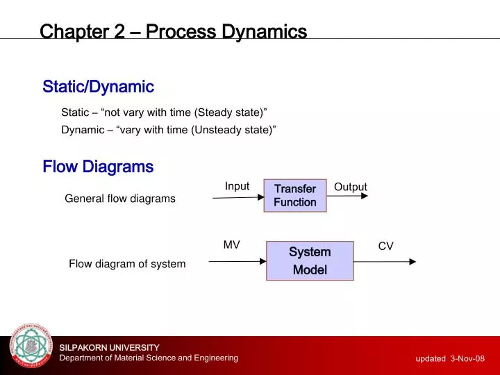
Chapter 2 – Process Dynamics. Input. Output. Transfer Function. MV. CV. System Model. Static/Dynamic Static – “not vary with time (Steady state)” Dynamic – “vary with time (Unsteady state)” Flow Diagrams. General flow diagrams. Flow diagram of system. Chapter 2 – Process Dynamics.

E N D
Chapter 2 – Process Dynamics Input Output Transfer Function MV CV System Model Static/Dynamic Static– “not vary with time (Steady state)” Dynamic– “vary with time (Unsteady state)” Flow Diagrams General flow diagrams Flowdiagram of system
Chapter 2 – Process Dynamics Part A: Numerical Solving - Finite difference method - Finite element method (FEM) - Finite volume method (FVM) Part B: Laplace Solving (analytical method)
Chapter 2 – Process Dynamics D Fin CA,in MV CV System Model CA h CA,in CA in Tank Fout CA,out Part A: Numerical Solving Case A: Conc. of A in tank (modelling) Flow Diagrams CA,out = CA
Chapter 2 – Process Dynamics Case A: Conc. of A in tank (modelling) Mass Flow Balance {rate of accummulation} = {rate of input} – {rate of output} + {rate of generation} – {rate of consumption}
Chapter 2 – Process Dynamics Case A: Conc. of A in tank (numerical) Finite Difference Numerical Solving
Chapter 2 – Process Dynamics Case A: Conc. of A in tank (on EXCEL) Numerical Solving
Chapter 2 – Process Dynamics Case A: Conc. of A in tank (on EXCEL) Numerical Solving
Chapter 2 – Process Dynamics D Fin CA,in MV CV System Model CA h Fin Level in Tank Fin CA,out Part A: Numerical Solving Case B: Level in tank (modelling) Flow Diagrams h orFout CA,out
Chapter 2 – Process Dynamics Case B: Level in tank (modelling) Mass Flow Balance {rate of accummulation} = {rate of input} – {rate of output} + {rate of generation} – {rate of consumption}
Chapter 2 – Process Dynamics Case B: Level in tank (modelling) Additional equation d = dia. of pipe
Chapter 2 – Process Dynamics Case B: Level in tank (Excel) Numerical Solving
Chapter 2 – Process Dynamics Case B: Level in tank (Excel) Numerical Solving
Chapter 2 – Process Dynamics Homework: 1. Create the excel file for simulate the dynamic of level and substance A concentration after increasing inlet flow from 36 kg/hr to 45 kg/hr and increasing the concentration of solute A from 0.2 to 0.4 kg_A/kg_solution.
Chapter 2 – Process Dynamics Steam Process Steam Heated Steam Homework: 2. Please modeling for studying temperature dynamic of process steam (assume dilute solution, FPS,in = FPS,out = 20 kg/hr, A=area of heat transfer=35 m2)which heated up by using steam at 2 bar, 393 K and what is the dynamic of system after inlet temperature of process steam decreasing from 30 ℃ to 26 ℃ PS , TS FPS,in , TPS,in FPS,out , TPS,out FC Condensate